About gpioX
A device that lets you connect sensors without breadboards or jumper wires,Want to interface an ultrasonic sensor?
Normally, you'd grab a breadboard and jumper wires and manually route the sensor’s pins to the microcontroller. This device removes that entire step. It provides universal GPIO pins where any pin can be configured in software to act as 3.3 V power, GND, or a signal pin. Sensors can be connected anywhere on the board, and their pin functions are defined digitally instead of physically. This simplifies wiring, reduces setup friction, and lets users focus on understanding sensor behavior rather than pin layouts.
The Idea (Simple Analogy)
Think about your laptop. It has many different connectors such as a charging port, USB ports, Type-C, HDMI, and Ethernet. Each of these ports has a fixed purpose, you can’t plug your charger into a USB port and expect it to work, because the function of each port is decided by the hardware itself.Now imagine a different kind of laptop where all the ports look the same. You could plug your charger into any port and it would work as a charging port. You could plug in a USB drive anywhere and that port would behave like USB port. In this imaginary laptop, the physical port no longer decides its function—software does.
That is exactly the idea behind this project, but applied to microcontrollers and sensors—connect hardware anywhere and define each pin’s role through software.
Problem with Traditional Arduino Wiring
When working with Arduino, sensors like ultrasonic modules usually have multiple pins such as VCC, GND, TRIG, and ECHO, while the required power and GPIO pins on the microcontroller are physically spread out. To get a sensor working, users typically have to:⇢ decide which Arduino pins will provide power and ground
⇢ connect the sensor’s signal pins to suitable GPIOs using jumper wires
⇢ use a breadboard to organize and distribute these connections
This physical wiring step can be tedious and confusing, especially for beginners who are still learning how microcontroller pin layouts work.
What This Device Does?
This device replaces fixed-function pins with 10 universal GPIO pins. Each pin can be configured in software to act as:⇢ GND
⇢ 3.3 V power
⇢ a GPIO signal
Instead of adapting your wiring to match the microcontroller’s pin layout, you simply connect the sensor to any available pins and define each pin’s role in software.
Example (OLED display):
Universal Pin 1 → GND
Universal Pin 2 → 3.3 V
Universal Pin 3 → SCL (GPIO22)
Universal Pin 4 → SCL (GPIO21)
The OLED behaves exactly as it would in a traditional Arduino setup, but without rearranging wires or worrying about physical pin placement.
Key Benefit
This shifts the workflow from
“How do I wire this sensor?”
to
“What should each pin do?”
How the Device Works (or How It Was Intended to Work)
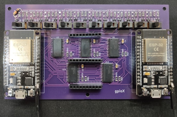
The device uses two ESP32 microcontrollers: a Main ESP and a Brain ESP.When you want to connect a sensor, you can plug it into any of the 10 universal pins on the board. These universal pins are connected to the Main ESP, but not directly. Instead, every pin is routed through a combination of multiplexers, N-channel MOSFETs, and P-channel MOSFETs. Based on the configuration set in software, each universal pin can act as a signal pin, a 3.3 V power pin, or a GND pin.
Each universal pin is internally connected to three outputs:
⇢ the output of a multiplexer, which carries a GPIO signal from the Main ESP
⇢ the drain of an N-channel MOSFET, which provides GND
⇢ the drain of a P-channel MOSFET, which provides 3.3 V
Since the signal path and power paths are electrically tied together at the universal pin, a physical slide switch is used to isolate them. For pins connected to a sensor’s VCC or GND, the switch is set to power mode. For pins used as signal input or output, the switch is set to signal mode. This ensures that power and signal paths do not interfere with each other.
The GPIO pins of the Main ESP are connected to the input channels of all multiplexers. The 3.3 V and GND rails of the Main ESP are connected to the sources of the P-channel and N-channel MOSFETs respectively. This allows the Main ESP to act as the actual source of power and signals for all connected sensors.
All multiplexers and MOSFETs are controlled by the Brain ESP, but not directly. Since the system includes 10 multiplexers, 10 P-channel MOSFETs, and 10 N-channel MOSFETs, the Brain ESP does not have enough GPIO pins to control everything on its own. To solve this, port expanders are used. The Brain ESP controls the port expanders, and the port expanders in turn control the enable pins of the multiplexers and the gates of the MOSFETs.
Why the Device Almost Worked as Intended
To drive a multiplexer, select lines S0–S3 and an enable pin are required. In the current design, the S0–S3 pins of all 10 multiplexers are connected in parallel and driven directly by the Brain ESP, while each multiplexer’s enable pin is controlled independently through the port expanders.Because the select lines are shared, all enabled multiplexers always select the same input channel. As a result, although the Brain ESP can enable any of the 10 multiplexers, it can only drive one multiplexer at a time with a unique signal selection.
This means the device works correctly for sensors or actuators that use only one signal pin, but fails for devices that require multiple independent signals at the same time, such as ultrasonic sensors, OLED displays, or other I²C-based peripherals.
This limitation could have been avoided if the S0–S3 pins of each multiplexer were driven independently using additional port expander pins. This behavior was later confirmed again through breadboard testing.
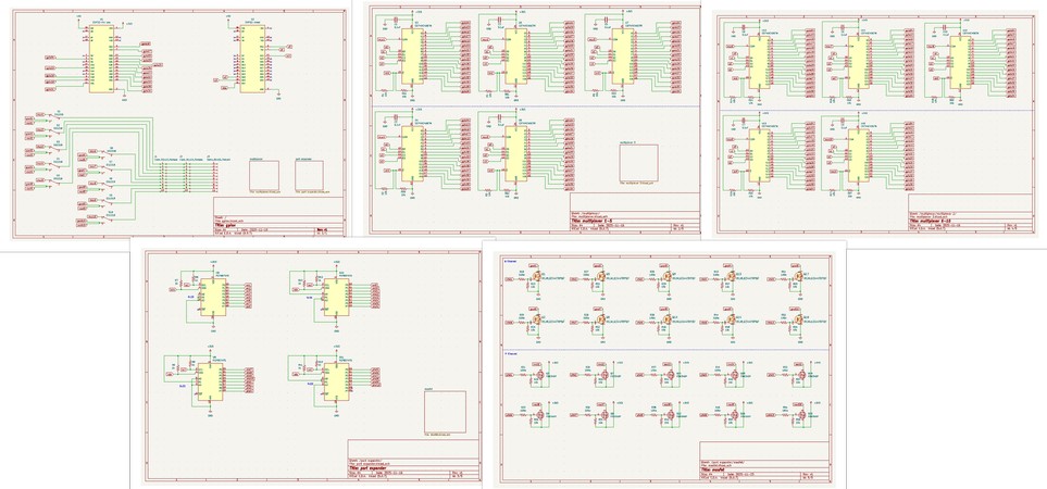
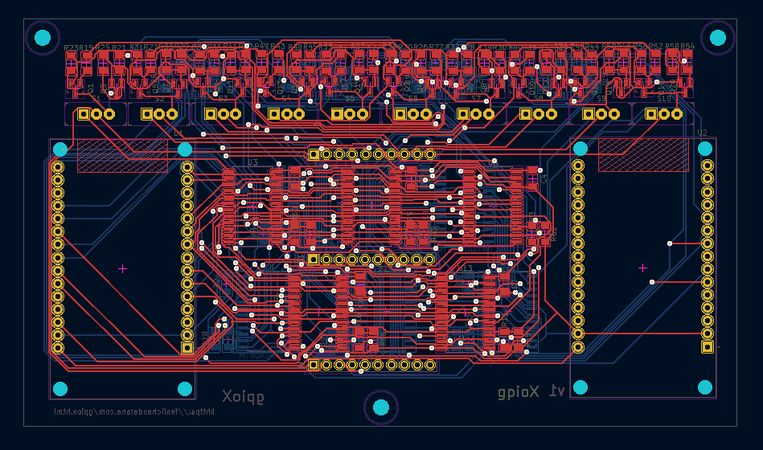
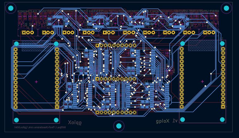
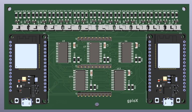
Dumping the captures during the building process,
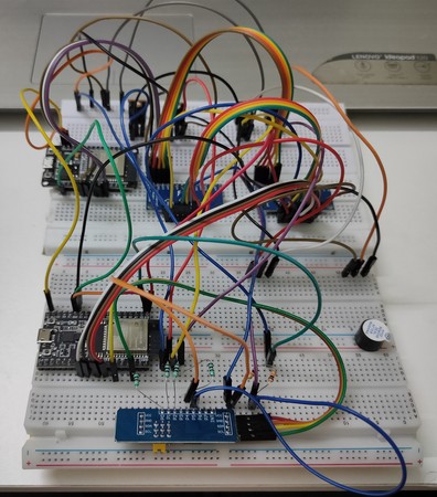
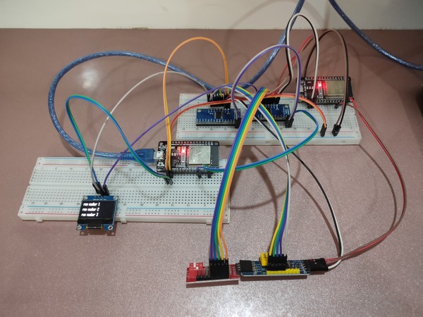
(Breadboard test confirming that independent S0–S3 control lines allow multiple multiplexers to be driven independently)
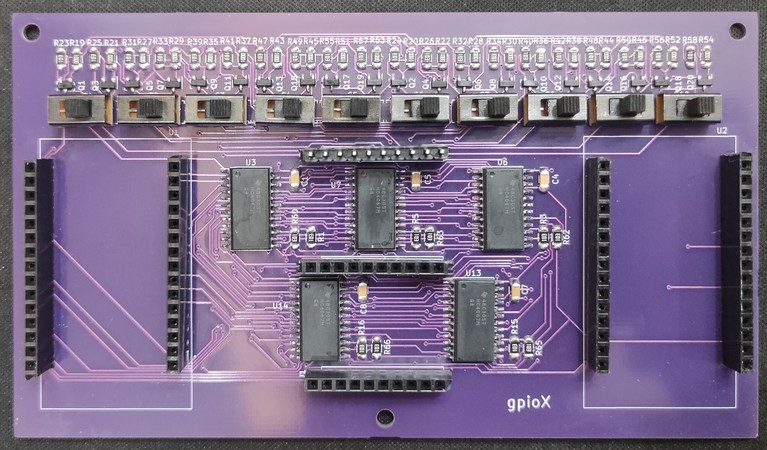
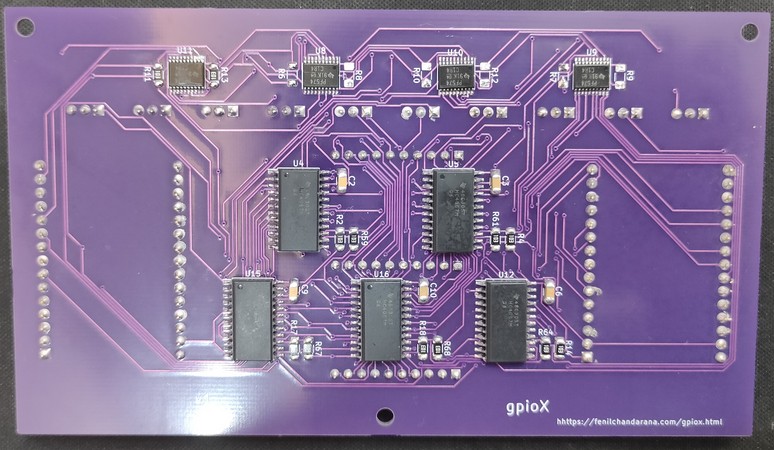
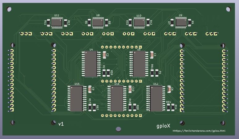
some snapshots of designing the PCB in KiCad. 127 components, 5 schematic pages, 2 layer PCB, 250 vias later: