About the machine
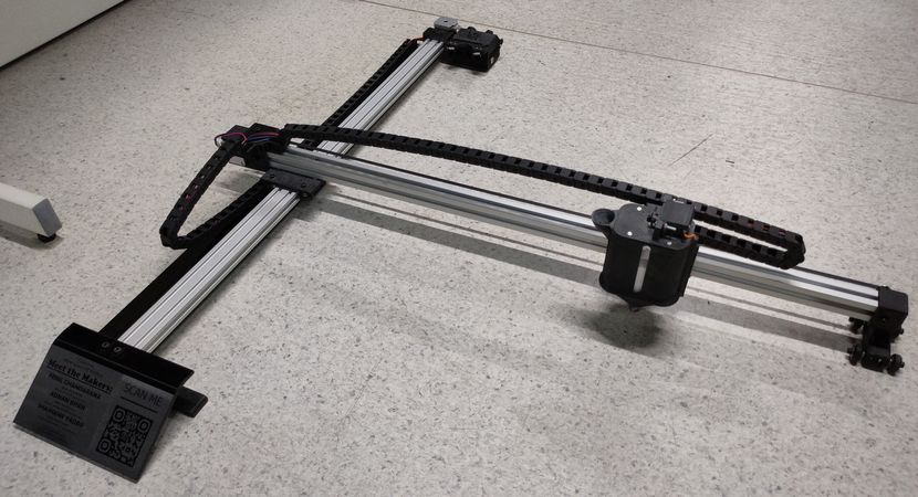
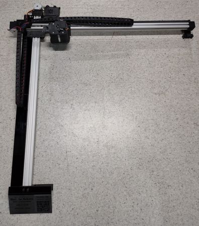
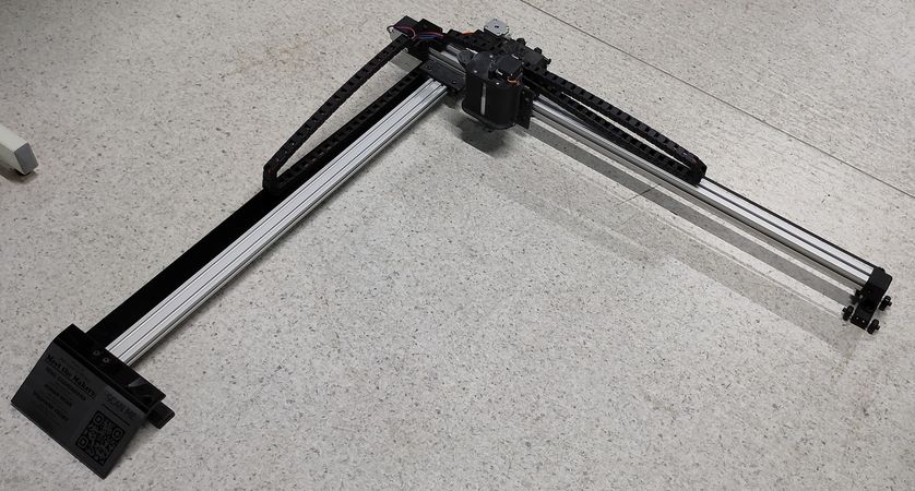
A one of a kind, 2-Axis CNC Rangoli Making Machine with a novel color-flow control
mechanism.
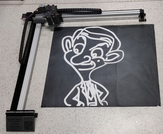
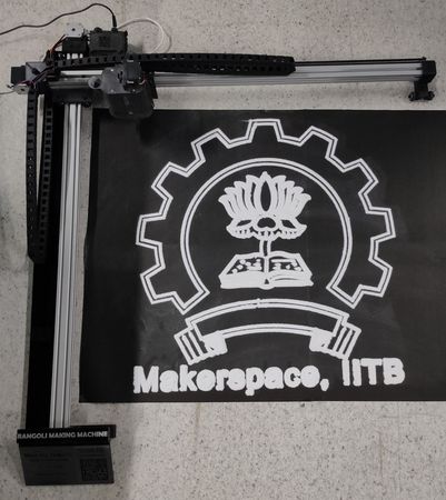
Here are some heroshots of the machine,
This project was developed with the support of Design and Making lab (Makerspace) IIT Bombay under the guidance of
Prof. Varun Bhalerao. The Makerspace provided the space,
machines, tools, equipments, raw material and funds required for the developement of the project.
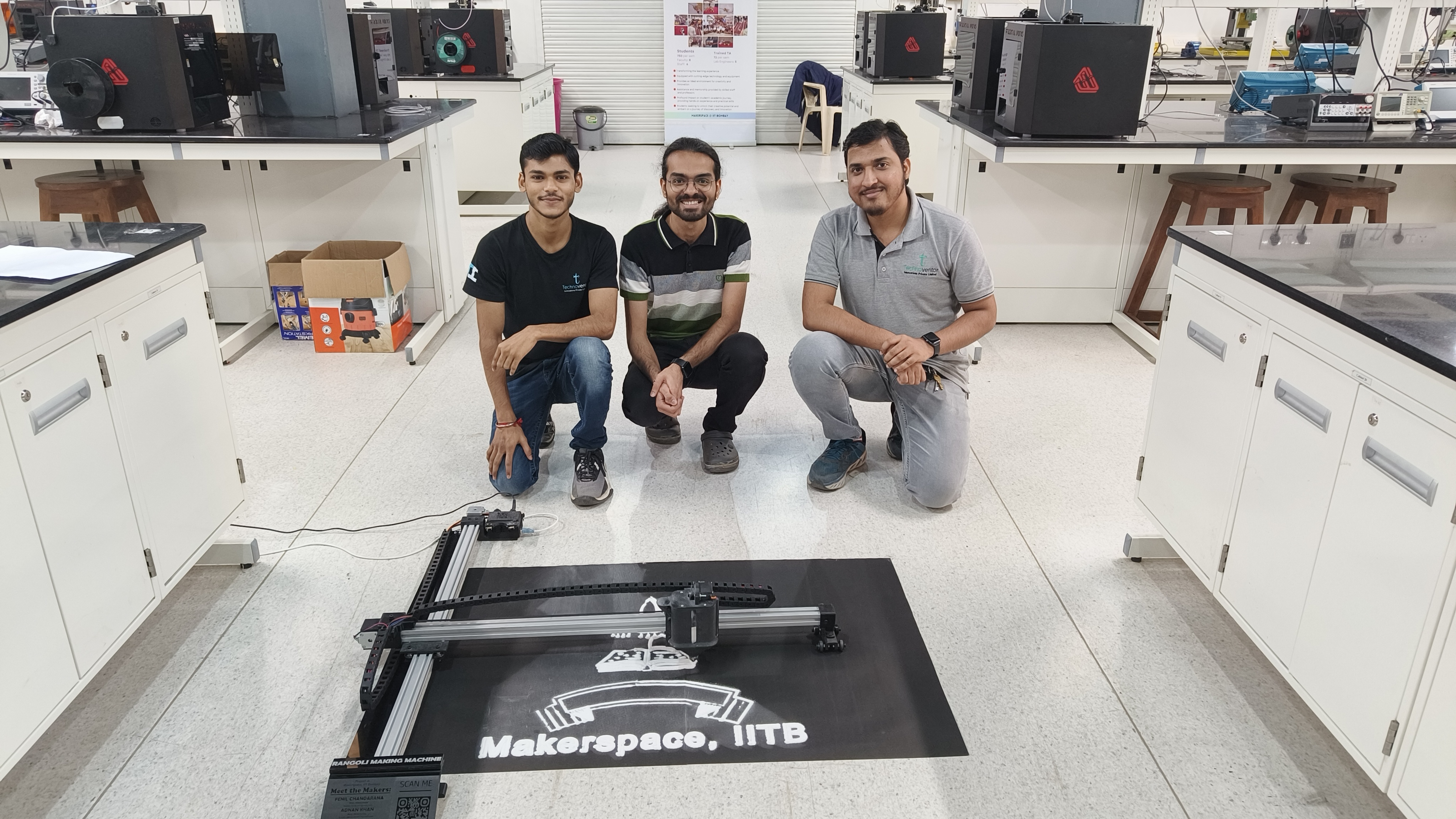
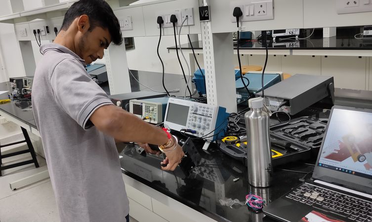
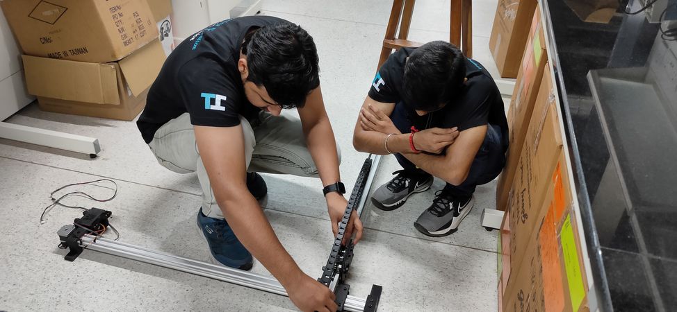
Meet the makers of the project: Adnan Khan (right),
Shashank Yadav (left) and
Fenil Chandarana, a team of Lab Engineers from
Technoventor Innovations
This was a self-initiated project and we developed this machine in our leisure time. It took us 4 months to complete the project- from ideation
to the final run of the machine. The project cost was under INR 15K.
Key Features
Some of the key features of this rangoli making machine are:More details regarding the features is given further below.
Contact the Makers:
Adnan Khan Contact number: (+91) 90217 94752
Email id: adnanrk007@gmail.com
LinkedIn: https://in.linkedin.com/in/adnanrkhan
Shashank Yadav
Contact number: (+91) 90227 34440
Email id: yshashank857@gmail.com
LinkedIn: https://in.linkedin.com/in/shashank-yadav-453745188
Fenil Chandarana
Contact number: (+91) 880 3330 330
Email id: fenil.c9@gmail.com
LinkedIn: https://www.linkedin.com/in/fenilchandarana
Click here to go back to the top
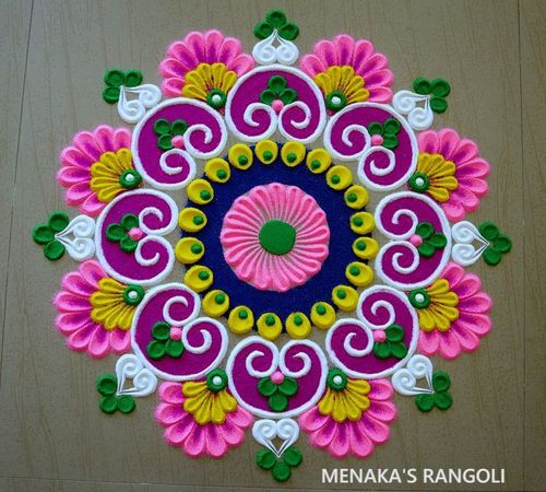
What is a Rangoli?
Rangoli is an art of decoration drawn meticulously and with bare fingers, it is meant to ward off all evils and is revered as a divine art.
It is thought to bring good luck, prosperity on the house and in the family, and to welcome guests.
Some mothers in India do this activity every morning, or on a special festive occasion like Diwali, Onam, and Pongal.
It is a folk art that is passed from one generation to another.
Rangoli patterns involve a floor design and are usually made on the floor, sidewalk, or entrances of homes using rice flour, chalk,
fine quartz powder, flower petals, grains or other
natural materials made of vegetable dyes. Drawing and connecting simple dots or lines is what usually creates these exquisite floor designs.
Most of the motifs are either geometric or they imitate the flora and the fauna.
Reference:
https://www.richlandlibrary.com/blog/2020-07-15/rangoli-creative-expression-indian-folk-art-through-use-colors
https://rangoli.org/what-is-rangoli
https://pin.it/381AGX1
Click here to go back to the top
Ideation
Between the semesters, since there were no training sessions and fabrication for the projects, we had some leisure time and wanted to
use this time effectively. We decided to develop a sophisticated machine in the Makerspace so as to show the strength of the lab and to leave
a mark behind. Something like this,
We talked to Professor Varun and he suggested to make a Rangoli Making Machine. His vision was to make a machine which can be used for the
inaugural events of the labs across the IIT Bombay. The machine should be sophisticated with intricate features while ensuring
user-friendly design for easy comprehension and yet tricky to replicate.
To achieve that goal, we would have to develop a machine that would be robust, portable, aesthetically pleasing and well-presented for
the inaugural events. Our objective behind making this machine was to utilize the makerspace facility so as to show the strength of the
makerspace apart from the curriculum that are conducted in the lab, to work on the project after our lab hours so as to not hamper our
daily duties and to complete the project under the proposed and approved budget of INR 15K.
Click here to go back to the top
Machine mechanism explored
Now that it was decided to make a machine which coud draw rangoli, we had to decide two things: Machine mechanism & Color-flow control
mechanism.
Here are the machine mechanism we considered:
Drawing robot
This is the kind of mechnism where there will be no limitation on the movement of the Y axis. Quite a unique and eye-catching robot however
considering few things like time, budget and resources available online for the reference, we decided to not go with this mechanism
for the rangoli making machine.
2 Axis cantilever machine based on CoreXY mechanism
The CoreXY mechanism was easy to work with lot of reference online on what hardware components would be required to make
one, how to assemble(Adnan has also worked with this mechanism) and also the components to make a CoreXY mechanism like guide rods, linear
bearing etc was comparatively cheap. The biggest advantage of this mechanism is that the machine would have looked very minimal and the view of
the rangoli while being made wouldn't have been blocked by the machine itself.
The only flaw is that we can't make a large size
rangoli with this CoreXY mechanism. We were planning to make the rangoli of approximately 700mm x 700mm(if the rangoli is of 700mm x 700mm the
size of the machine would be even larger). Since there is no suport on the ends of X axis
rods, the machine would topple if we make the machine of that size and also we were estimating that we would require
to have a container which can carry atleast 1KG of rangoli color. With that size and weight, CoreXY was not feasible to go with.
If we wanted to go for the CoryXY mechanism, we would have to make box like structure where the nozzle is moving inside the boundry and
that would have made the machine very bulky and it would block the view of the rangoli during its making,
2 Axis cantilever machine based on cartesian mechanism
This cantilever cartesian mechanism was the one we fund most feasible to work with given our desired size of rangoli and color we wanted to
carry. This mechanism too is very popular and we would easily find the reference of the hardware components and instructions regarding the
assembling. Since the Y axis aluminium extrusion had support on both ends, we were planning to add a caster wheel like element on the X axis
aluminium extrusion as well so that the machine can carry the load of the color when the color container/hopper reached extreme end of the
X axis.
For the color container/hopper we wanted to add a mechanism onto the nozzle
which can control the flow of the color so that the color doesn't flow while the
hopper is travelling from one point to other or the color doesn't flow when it shouldn't, just like the pen plotter where the servo motor
will lift the pen up and down.
Click here to go back to the top
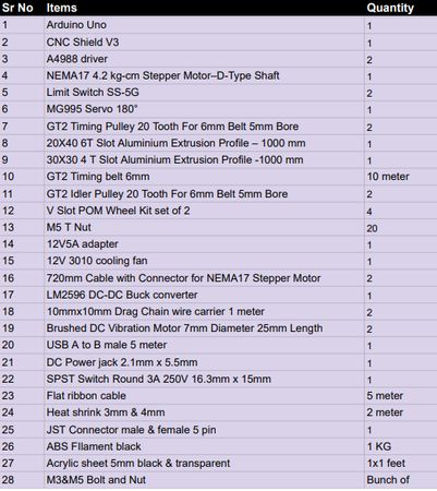
Bill of material
We prepared the Bill of material for procuring the materials.
The material required to make the Rangoli making machine is majorly divided in 3 categories: Electronic components, mechanical components and
raw material for fabrication.
Electronic components
Mechanical components
Raw material for fabrication
Below is the list of all the items mentioned above with quantity:
PDF of BOM
Click here to go back to the top
Color-flow control test
Since we wanted to control the color-flow from the hopper, we had to think some kind of mechanism for that and accordingly we had to think
the design of the hopper considering the hopper should be able to carry atleast 1KG of the color.
Water bottle
Initially we filled the color inside a water bottle and checked the flow of the color by drilling a hole on the cap,
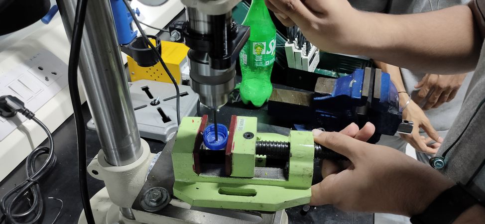
Drilled hole on the bottle as well for the air flow,
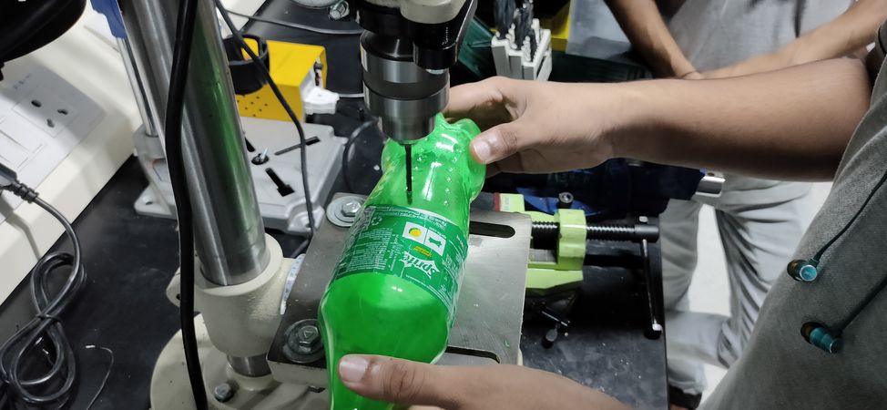
We found that the color was not flowing without squeezing the bottle,
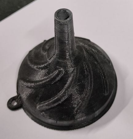
3D printed nozzles
We 3D printed some small nozzle in vase mode and drilled a hole of 3-4mm and tried pouring color through it,
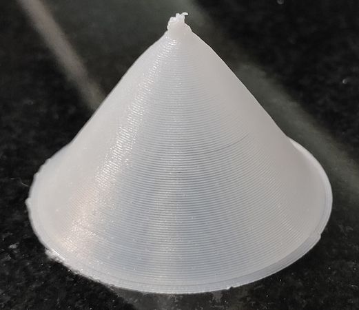
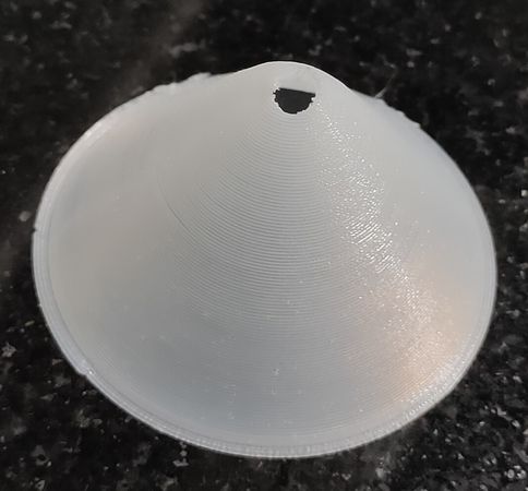
The color was still not able to flow without squeezing the nozzle or some external jerks.
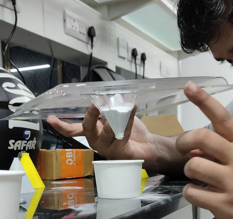
Molded nozzle
We assumed that the reason why the color was not flowing was because of the surface finish of the inside of the 3D printed nozzle. We thought
that because the finishing of 3D printed nozzle was not smooth, the color was not flowing properly.
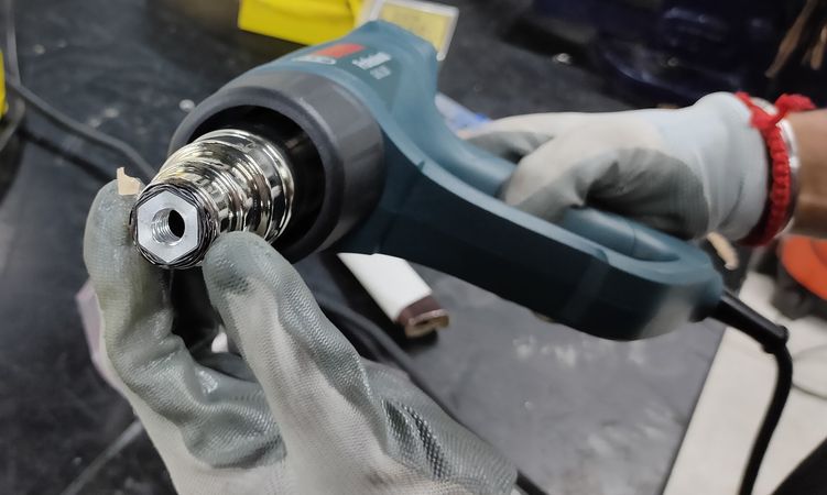
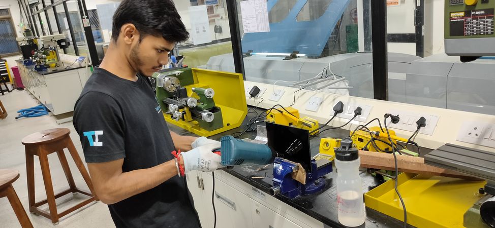
So we tried using cast sheet to form the shape of the nozzle using vacuum forming machine and later drilling the hole.
The finishing of the cast sheet was very smooth so
we assumed that the color should flow freely through the molded nozzle.
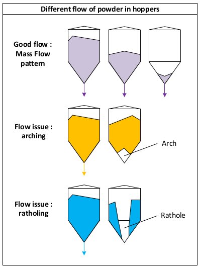
The color was still not smoothly external jerks. We then realised that the surface finish of the the nozzle was not the issue. The issue was that the color was sticking
to the side of the nozzle after some point. This phenomenon is called Rat-holing effect. Rat-holing occurs when the material cakes on the vessel walls
3D printed nozzle with vibration motor
Now that we had figured out the actual problem, we came up with a solution of attaching vibration motor onto the nozzle. The vibration motor will provide external jerks and
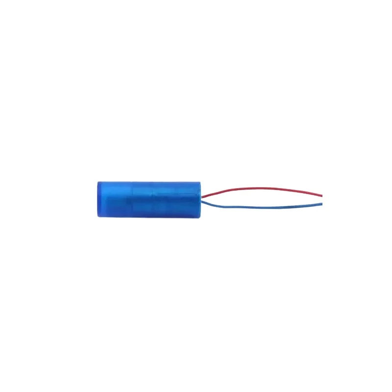
vibration to eliminate the rat-holing effect. We initially used the small coin-shaped vibration module,
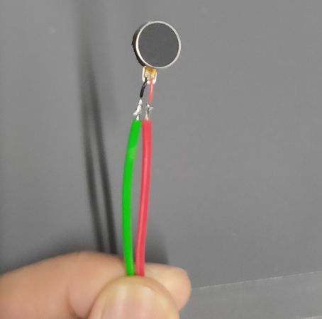
Here is the vibration module eliminating the Rat-holing in effect,
Controlling the flow of the color
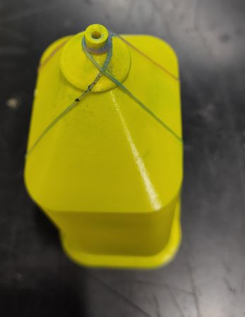
Now that we ensured a continuous smooth flow of the color through the nozzle, we had to figure out a way to stop the flow as well. Controlling the flow of the color by just turning the vibration motor ON & OFF was not enough because sometimes even without any external vibration the color would flow,We thought of some mechanism to just block the hole of the nozzle to stop the flow of the color and we came up with the idea to use bicycle spoke to block the hole of the nozzle. To test that theory, we designed and 3D printed a single body hopper,
the hole of the hopper was too big so we 3D printed a small nozzle to attach onto the nozzle,
we tried to manually poke the spoke first(no rhyme intended),
later we attached the spoke onto the servo motor,
the theory seemed to work so we decided to go with this mechanism. While doing initial test, we were using MG90 servo motor with just one piece of acrylic sheet working as a link between the motor shaft and spoke, but as we progressed, we switched to MG995 and developed a 3 part linkage to move the spoke upwards and downwards. More on that in the next section.
Click here to go back to the top
Designing
The designing of the Rangoli making machine is divided in major two sections:
Adnan Khan designed the whole Rangoli making machine - the hopper as well as the mating parts in Autodesk Fusion 360.
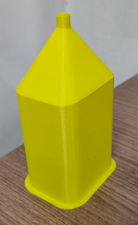
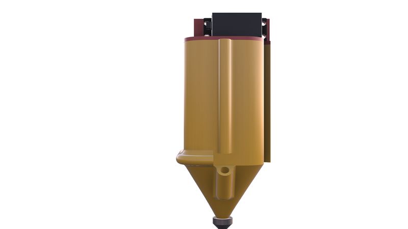
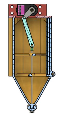
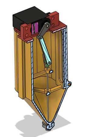
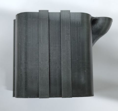
Designing of the hopper
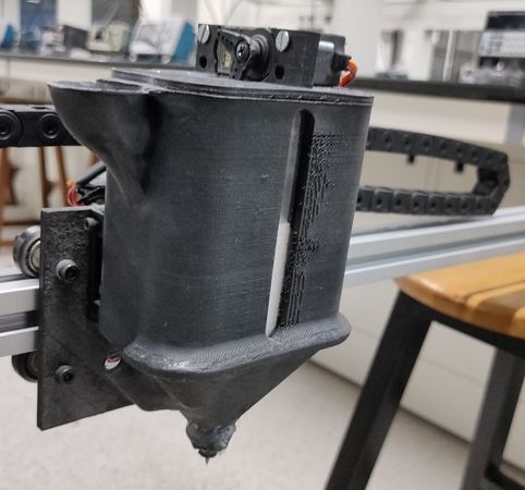
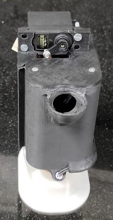
The hopper is the novelty of the rangoli making machine, something that is custom designed and developed as per the application, 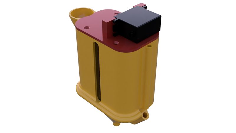
These are the key features of the hopper,
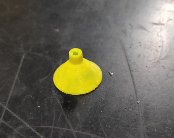
In-built funnel for pouring the rangoli color
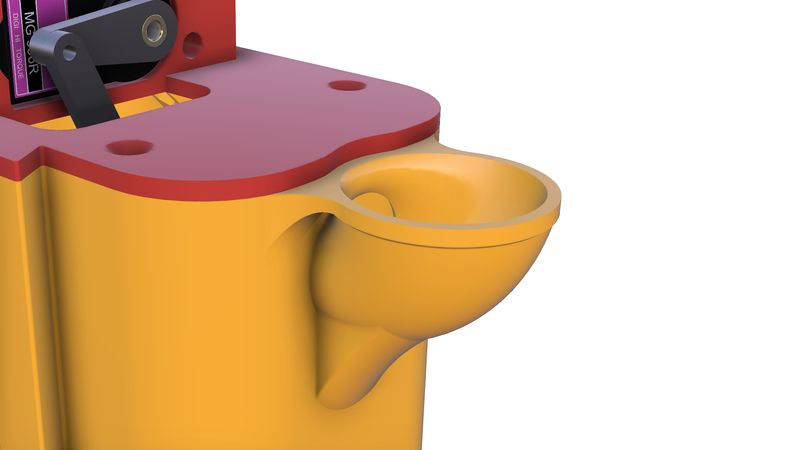
For the ease of pouring the rangoli color and also to empty the container completely, we designed an in-built funnel like shape at the top of the hopper. We designed and fabricated an external funnel as well to fill the rangoli color more quickly,
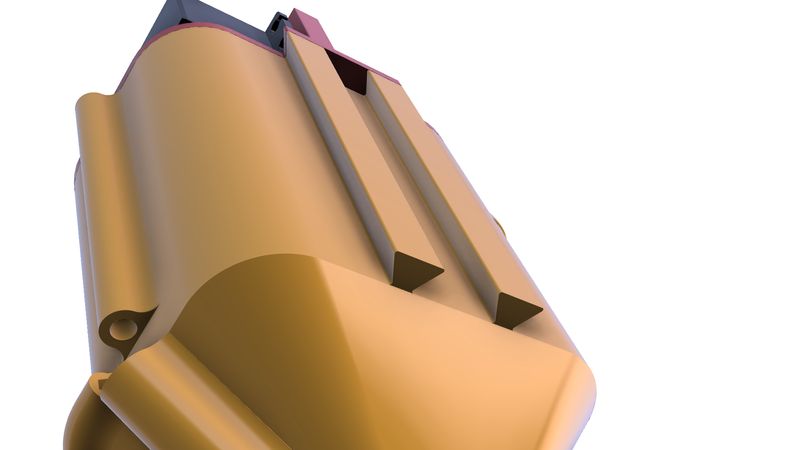
Color level indicator
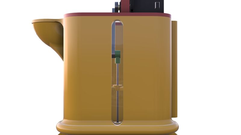
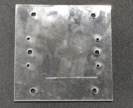
To get an indication about how much color is left in the hopper, we gave a provision of a slot where we would insert a transparent arcylic sheet.
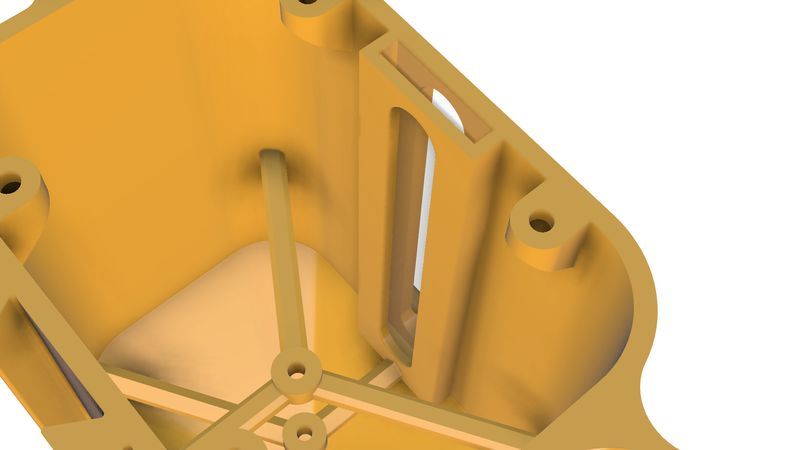
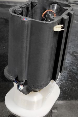
Vibration module on two ends
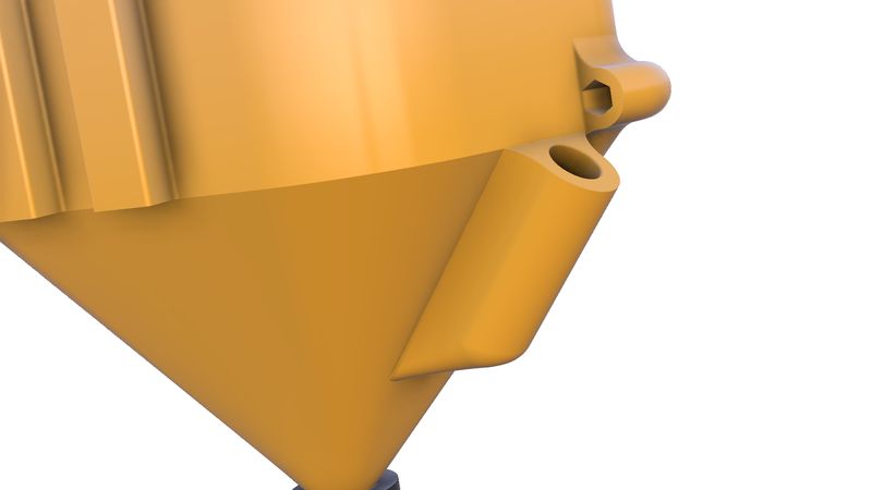
To eliminate the Rat-holing effect and to ensure smooth continuous flow of the color, we gave provision of placing vibration motor on both ends of the hopper near the nozzle.
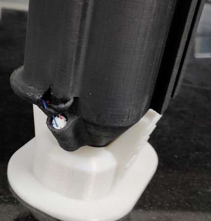
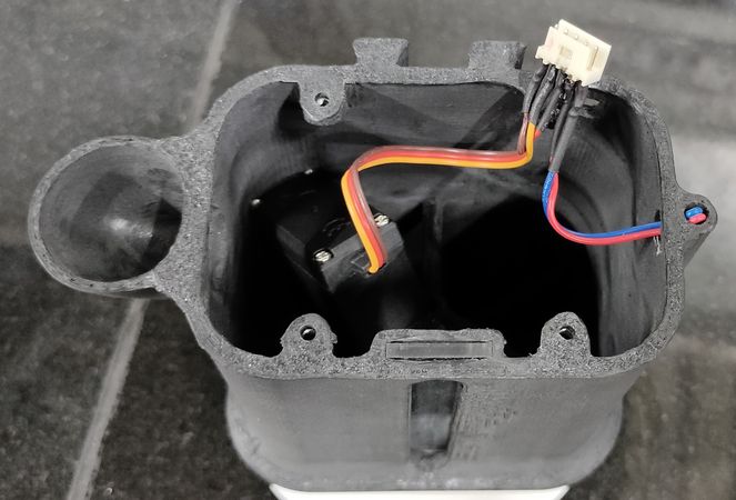
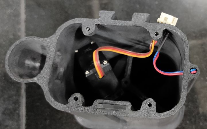
Tunnel for routing the wires
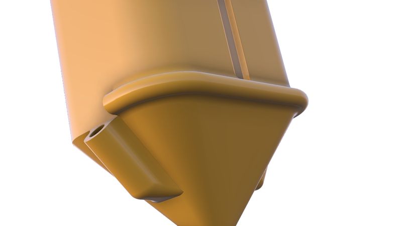
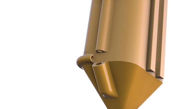
To route the wires of both vibration motor with the servo motor on the lid in a way that wires are well hidden, a tunnel ws designed around the hopper.
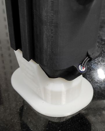
Detachable hopper
To make the hopper mechanically detachable, we decided to design Dovetail mechanism where the male dovetail will be on the hopper and the female dovetail will be on the machine,
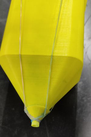
Guide for the spoke
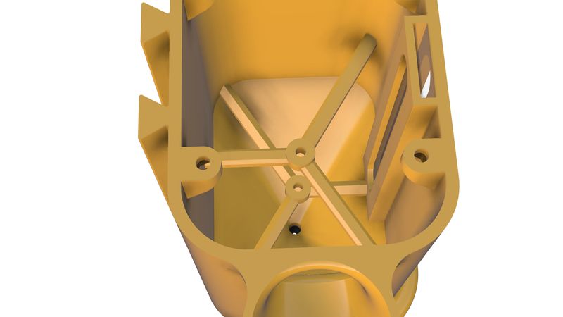
To restricct the horizantal moveent of the spoke when it is plunging downwards and upwards, we gave provision of two guides inside the hopper
Working
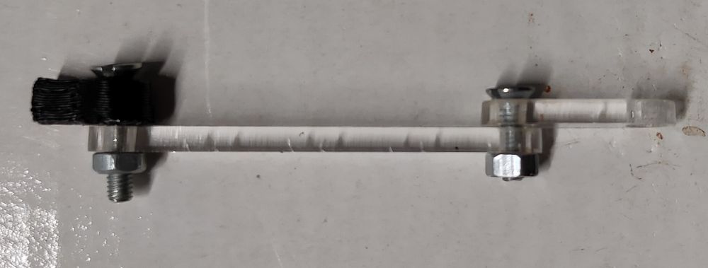
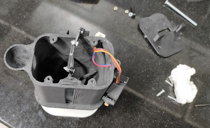
The spoke plunges upwards and downwards through servo motor with the help of three linkages,
The final verison of the hopper was made after several iterations. Here is the brief description of all the older version of the hopper,
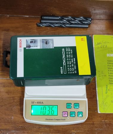
Single part nozzle printed in vase mode andd using detachable nozzles of different sizes of holes from 3mm to 5mm for testing purpose. 3D printed the part so that we can also measure the weight of the color and modify the design if necessary,
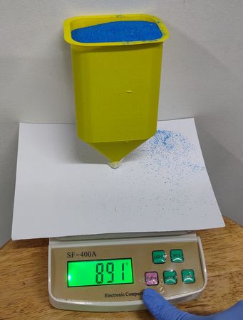
using different detachable nozzles for the hopper,
this is us calculating how much color(weight) flows in a minute so we can estimate how much big of a rangoli we can make with the machine
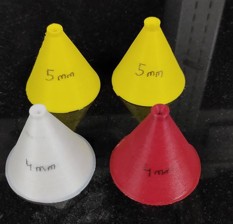
(4mm and 5mm nozzle with and without fillet)
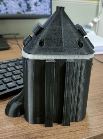
We modified the size of the hopper so that we can fill approx. 1KG of rangoli color. We also re-designed the hopper in 3 parts:
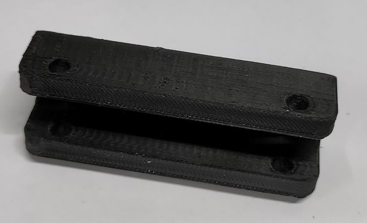
The lid that will have the provision of mounting the servo motor
The container having slot for inserting transprent arylic sheet to see the color level inside, provision of tunnel for routing the wires and guide for the spoke
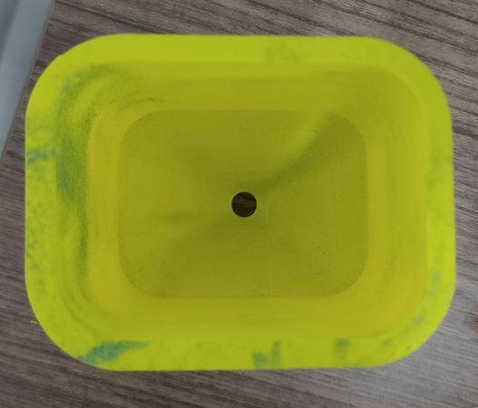
And the last part is the nozzle having provision for mounting the small vibration motor with the tunnel to route the wires.
Other features included: added a in-built funnel on the hopper for easily filling the color, dove tail mechanism for easy detaching of the hopper from the machine.
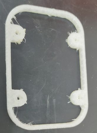
We even tried to add a TPU printed layer to squeeze it between the container and nozzle to completely seal the container, ensuring no leak of the color from the hopper,
For the final version of the hopper we made small iterations like made the hopper in two parts: lid and container with hole of 2mm for the color to flow, increased the shape and diameter of the tunnel for easy routing of the wire, used a larger size vibration module, provision for MG995 servo motor instead or MG90, detailed description of which is mentioned above.
Designing of the mating parts
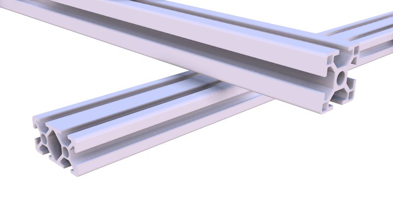
To make the 2 axis rangoli making machine we were using mechanical components like T slot aluminium extrusion, pulley, timing belt, Vslot wheels
etc. To assemble those coponents we designed and fabricated mating parts. Y axis sliding Vslot wheel assembly
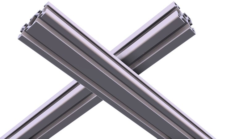
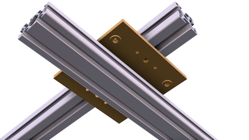
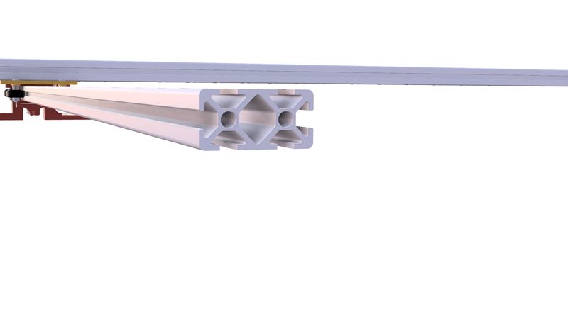
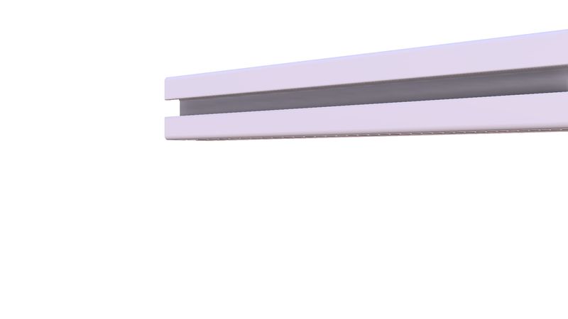
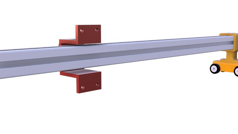
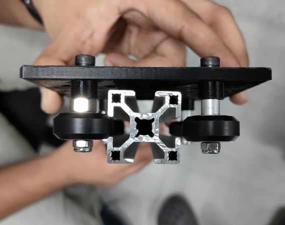
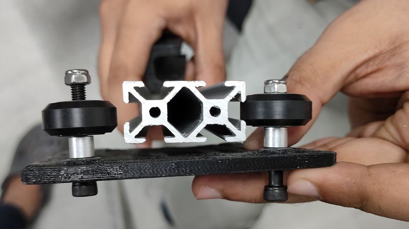
We were using 30x30 mm aluminium extrusion for the X axis and 20x40 aluminium extrusion for the Y axis.
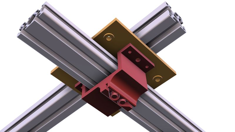
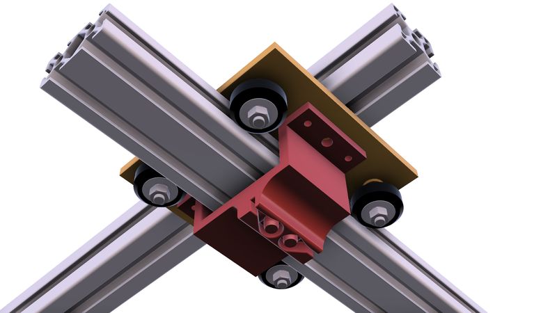
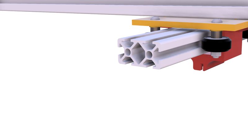
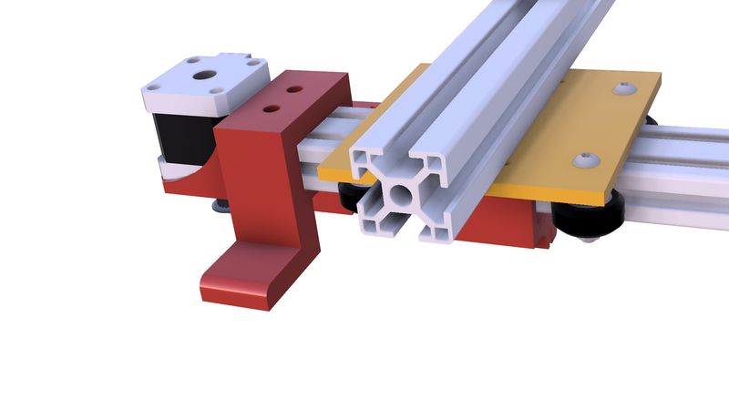
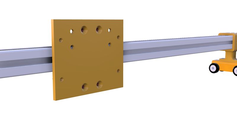
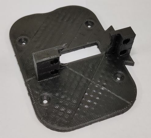
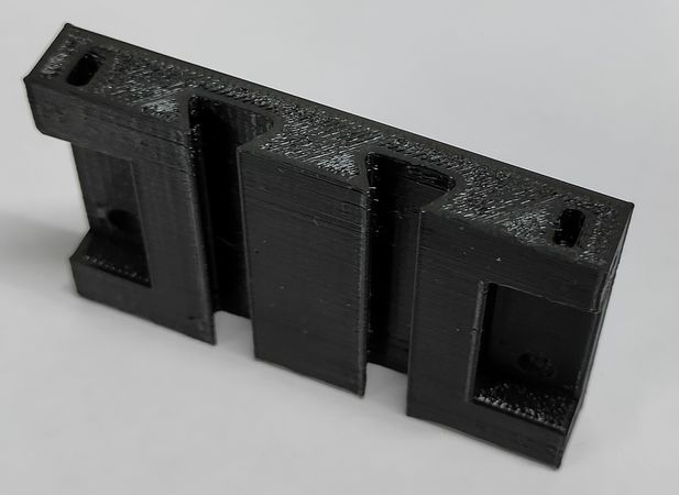
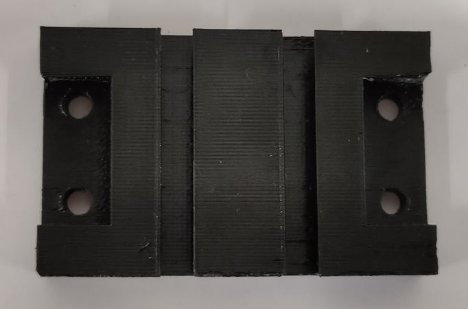
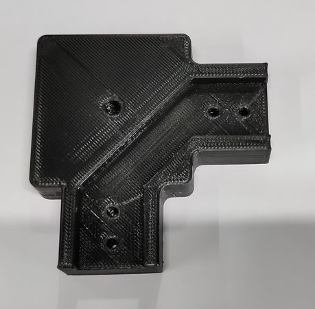
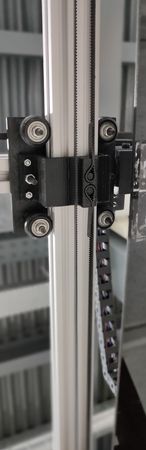
For the X axis aluminium extrusion to slide onto the Y axis aluminium extusion, there is a plate with four Vslot wheels onto which the X axis aluminuim extrusion is fixed and onto that same plate, there is a part that locks the open loop timing belt,
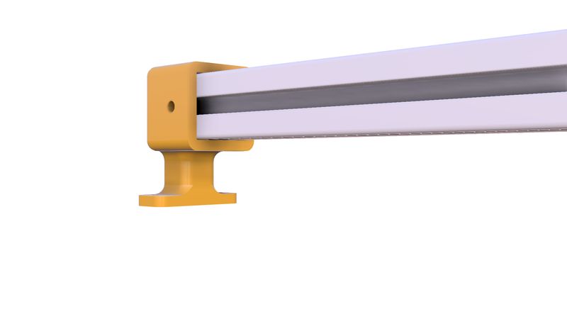
Platform for Y axis
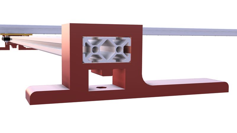
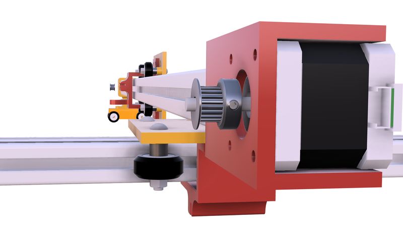
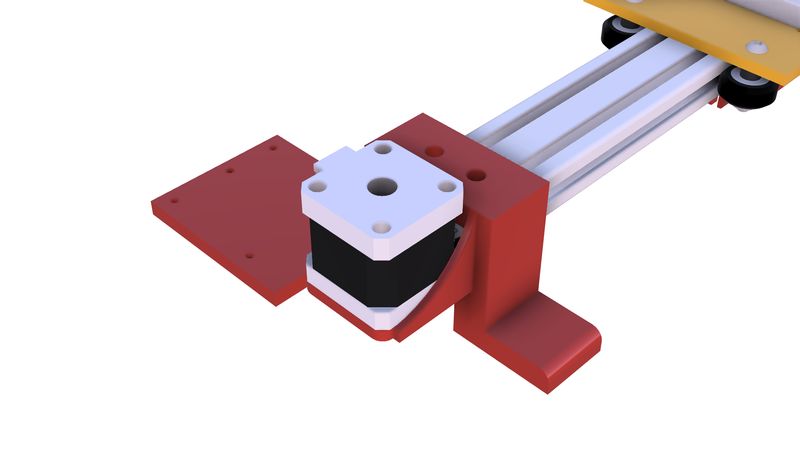
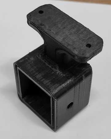
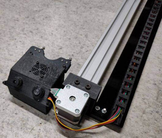
On both end of the Y axis there is a platform to raise the aluminium extrusion. On one end(near home position) there is a platform with the provision to mount stepper motor,
on the other end of the Y axis (extreme end) there is a platform to mount idler pulley,
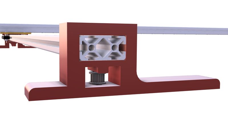
the open loop timing belt is wrap around the pulley onto the Y axis stepper motor and the Y axis idler pulley and the open ends of the timing belt is locked onto the locking part under the Vslot wheel plate.
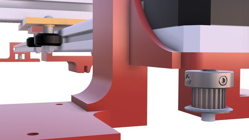
So when the Y axis stepper motor rotates it will cause the X axis aluminium extrusion to slide onto the Y axis.
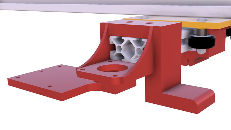
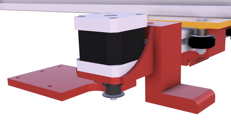
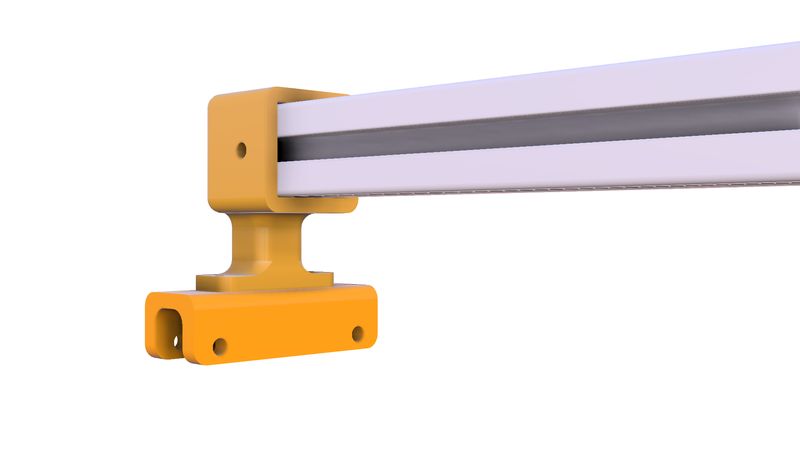
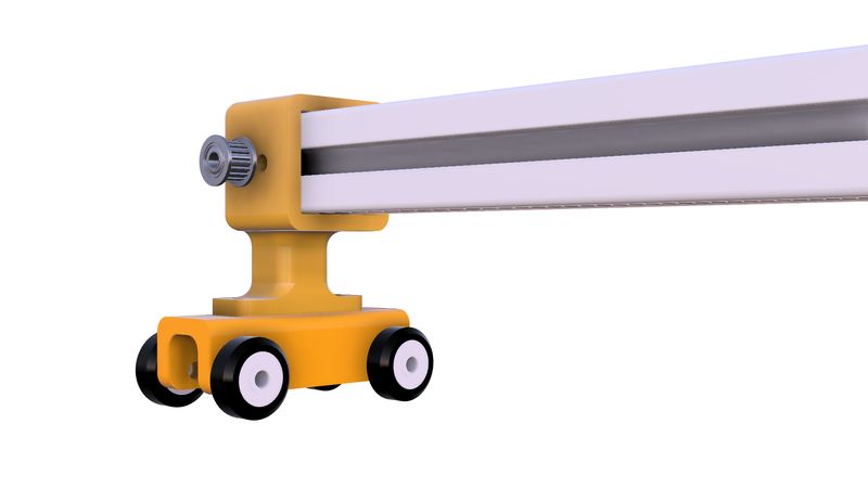
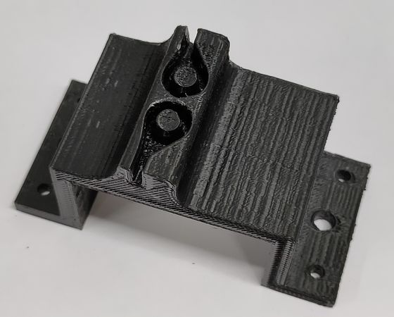
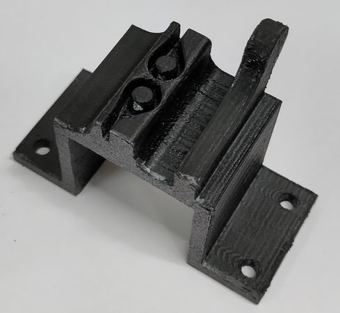
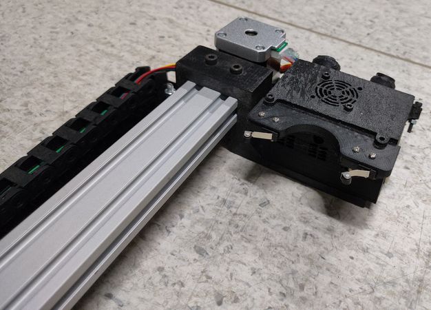
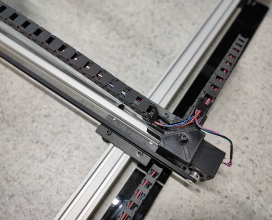
Platform for X axis
On one end of the X axis(near home posiition) there is a part with the provision to mount stepper motor,
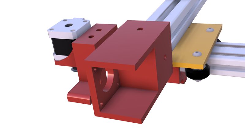
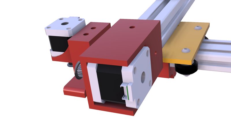
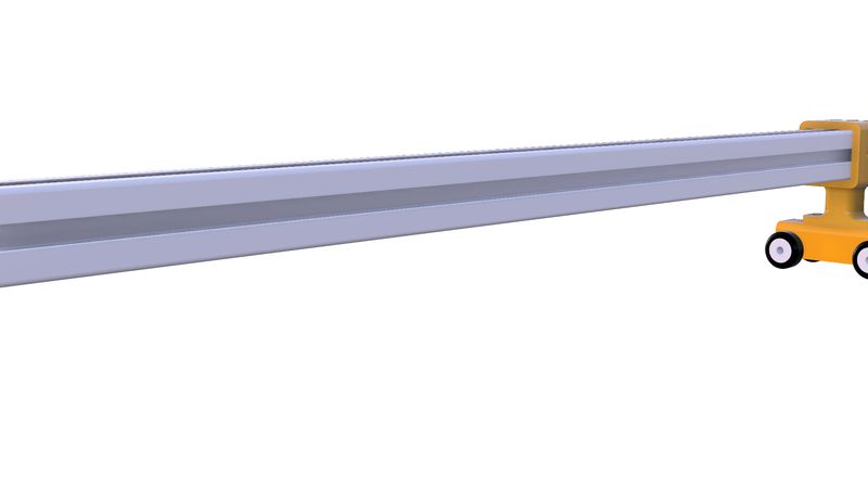
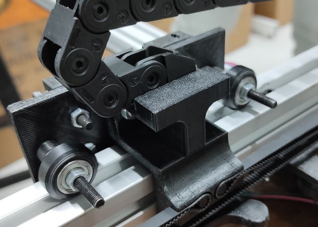
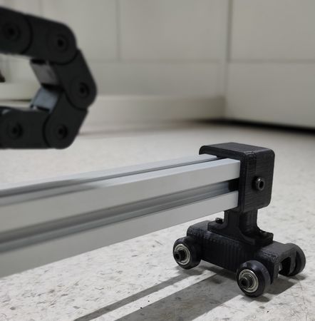
on the other end of the X axis there is a caster-wheel like assembly with the provision to mount idler pully along with Vslot wheels on the bottom to balance the X axis aluminium extrusion so when the X axis aluminium extrusion is sliding on the Y axis, the X axis aluminium extrusion remains perpendicular to the Y axis aluminium extusion,
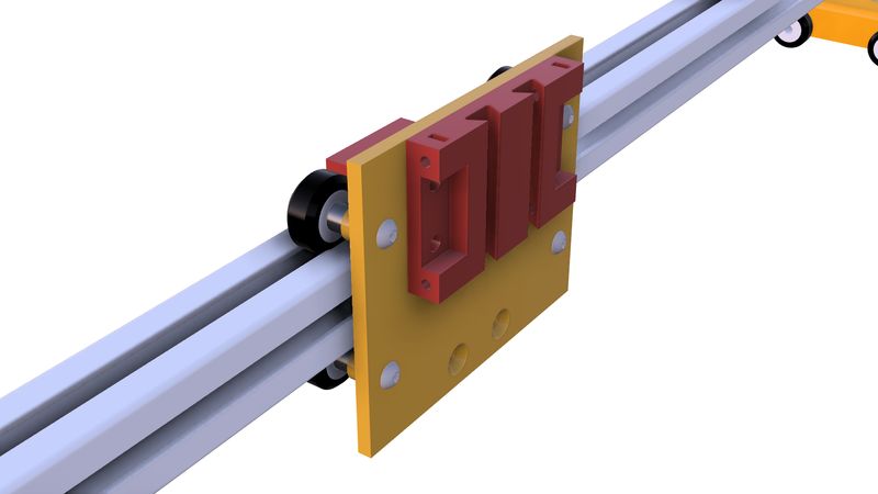
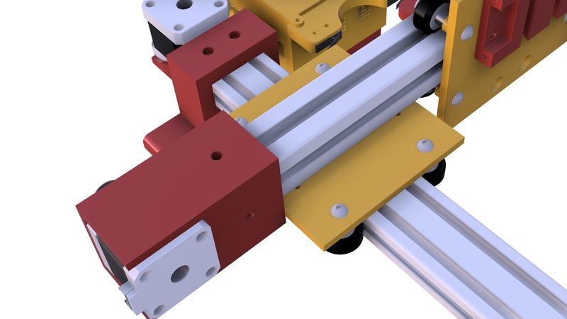
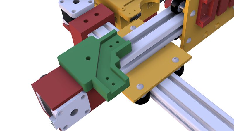
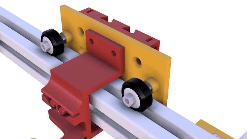
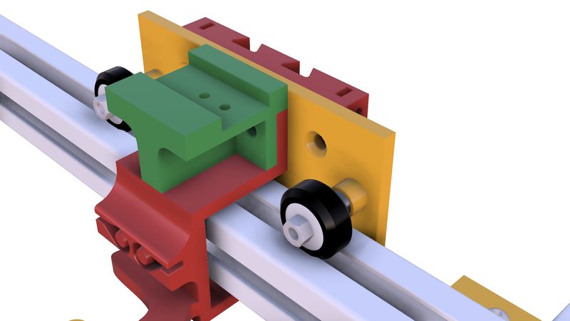
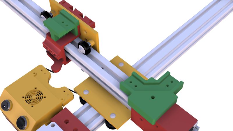
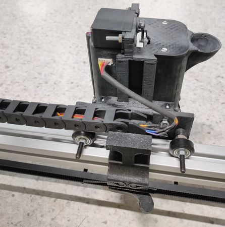
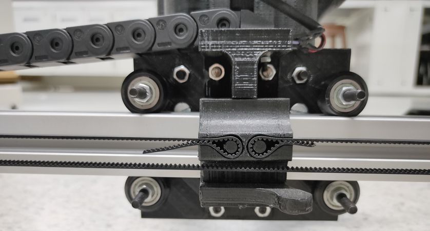
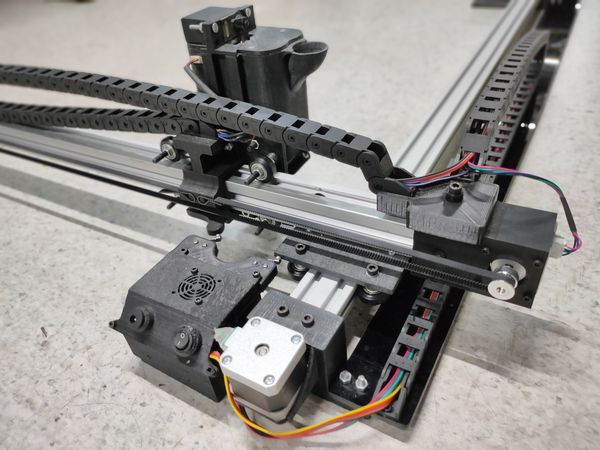
X axis sliding Vslot wheel assembly
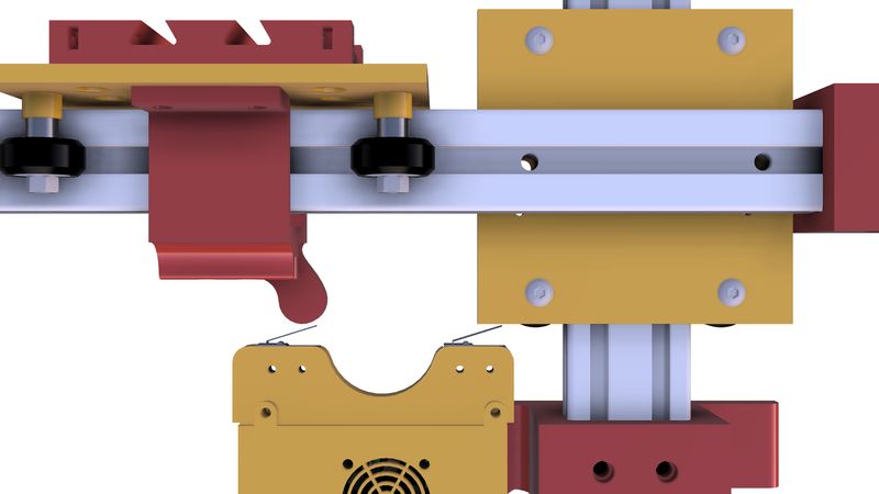
Just like there was assembly of four Vslot wheels for the X axis aluminium extrusion to slide on Y axis aluminium extrusion, there is a plate onto which four Vslot wheels are mounted along with the locking part to fix the open loop timing belt,
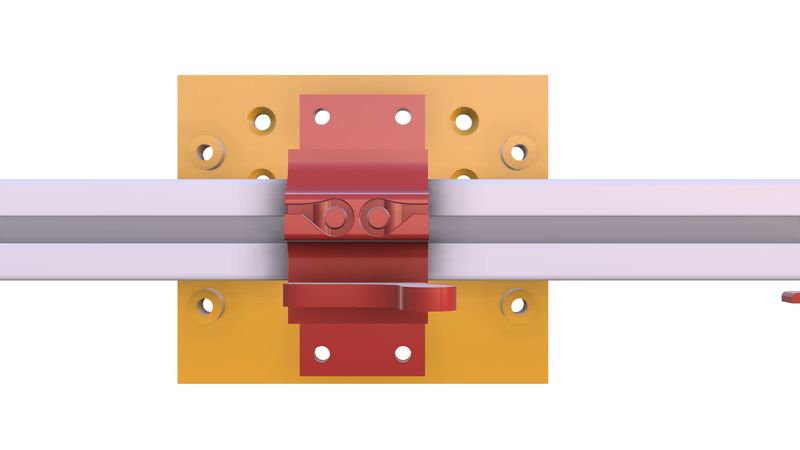
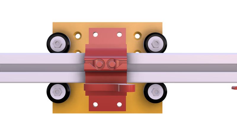
onto this plate of four Vslot wheel assembly, we have mounted female dovetail to mount the hopper,
the open loop timing belt is wrap around the X axis stepper motor and the X axis ider pulley and the open ends of the timing belt is locked onto the locking part under the Vslot wheel plate,
So when the X axis stepper motor rotates it will cause the hopper to slide onto the X axis.
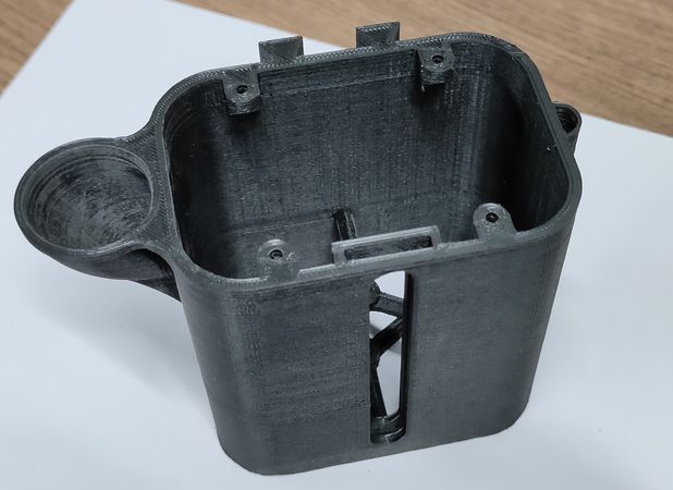
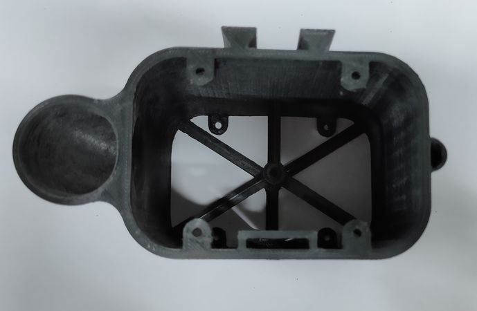
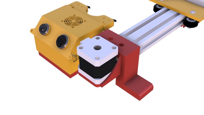
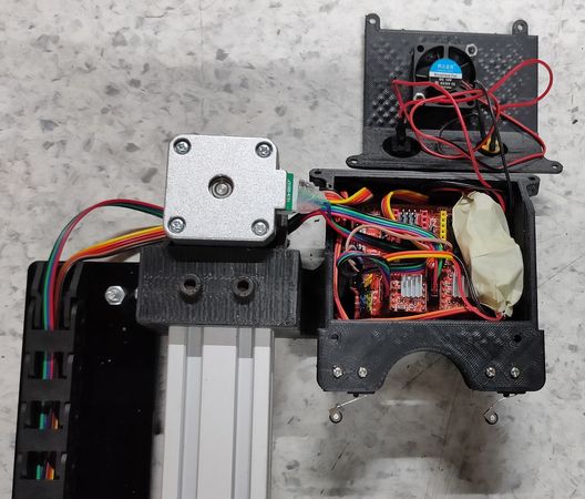
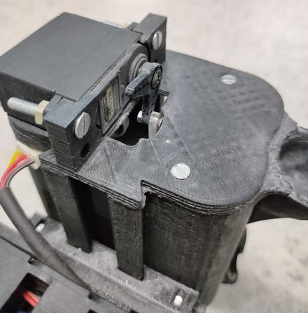
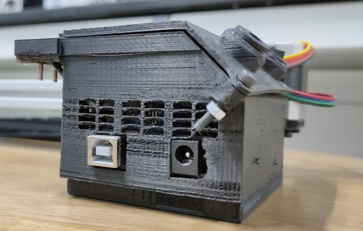
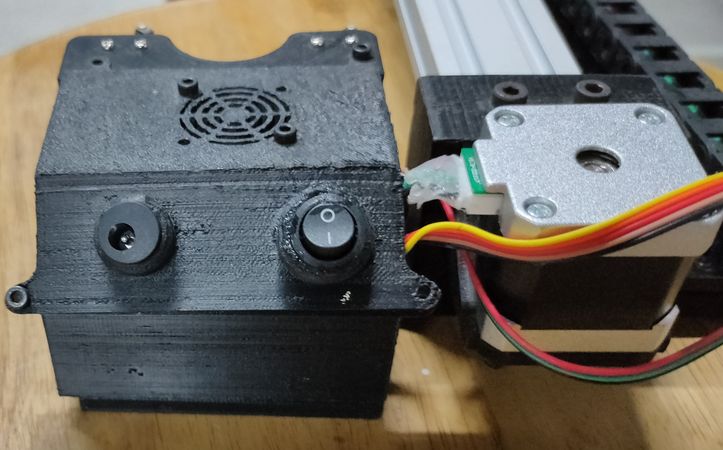
Housing of the electronic components
To place the electronics components like Arduino UNO, CNC shield, Buck converter, limit switches, fan we designed a case to house these components and gave provision of slots to mount DC power jack, SPST switch and to attach the cable for UNO. The housing is on the Y axis near home position,
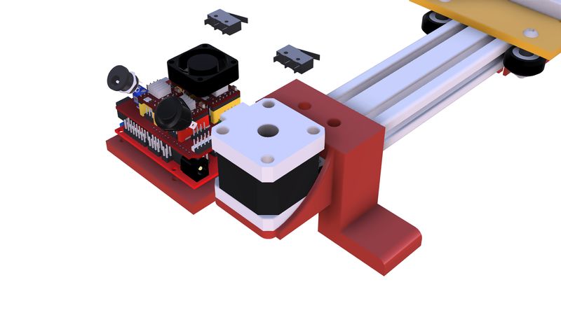
The limit switch for both the axis is on the Y axis. The homing sequence should be Y axis first and then X axis for this case,
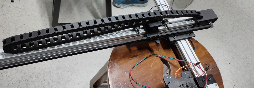
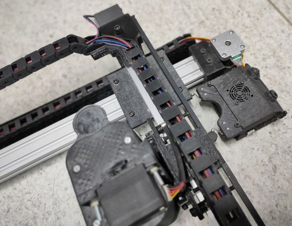
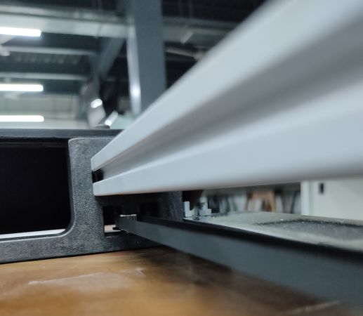
Mount for dragchain
For routing the wires of stepper motor, servo motor and vibration motor we were using dragchain. To attach those dragchain we designed the part and mounted onto the X axis stepper motor housing,
and we mounted another part onto the Vslot wheel assembly plate for X axis,
To support those dragchain from the bottom so that the dragchain doesn't hang, we attached a plate onto the platform of Y axis,
Click here to go back to the top
Fabrication
The designing and fabrication part was going on simultaneously, like once we fabricate the part, we test it and if there were any iterations
necessary we would change the design and re-fabricate. We used two methods of the fabrication: 3D printing and laser cutting.
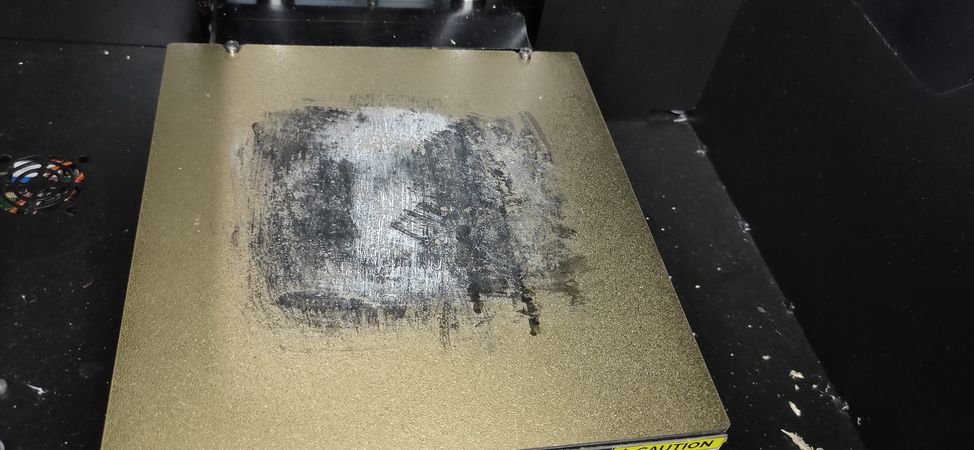
For 3D printing we decided to use ABS filament for better quality and durability of the parts. Printing the parts with ABS is a little tricky.
Initially we used to print the parts directly on the bare buildplate but after printing a few minutes, the initial layers would start
to peel off from the buildplate.
We stick paper tape onto the build plate and sprayed hair spray onto the paper tape for better adhesion(Source: Trust me bro),
the part would print but there would be some warping on the initial layers which would not give you a flat surface and that is why
we had to squeeze a TPU printed layer between the container and nozzle to seal any gaps.
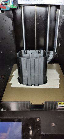
We then found out that the best way for the ABS to stick onto the buildplate throughout the printing process without any warping is to
apply a layer of ABS slurry onto the buildplate. ABS slurry means dissoling ABS into Acetone which will liquidify the ABS,

Note: Every printed part other than black color that you see in the documentation is printed in PLA filament for testing purpose since it is
easy to print.
Here are some snapshots of the 3D printed parts, design of which is mentioned above in Design section,
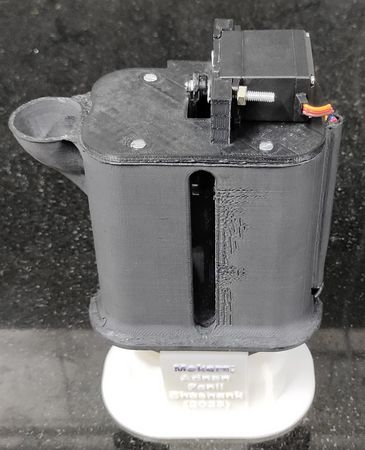
lid of the hopper
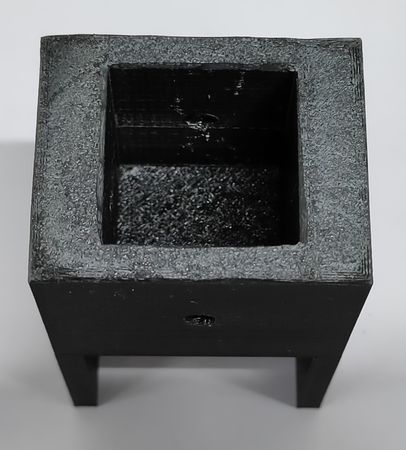
container of the hopper
X axis Vslot wheel assembly plate
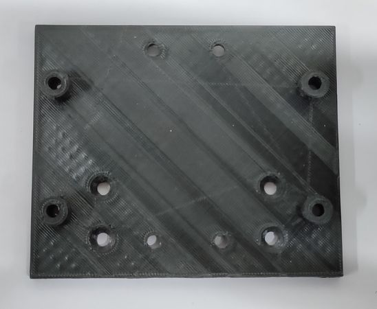
Y axis Vslot wheel assembly plate

X axis stepper motor mount
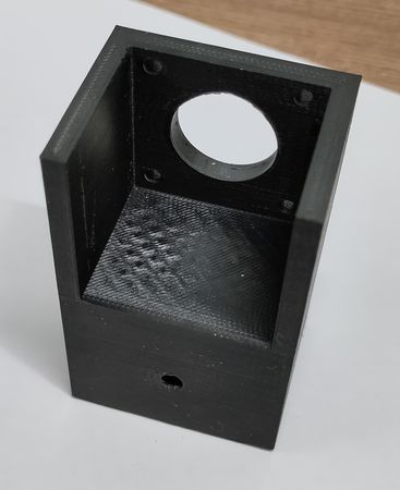
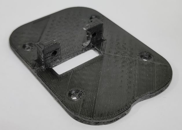
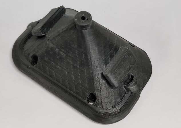
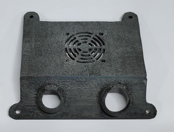
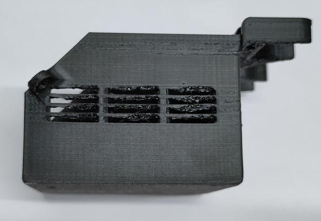
Electronics housing lid
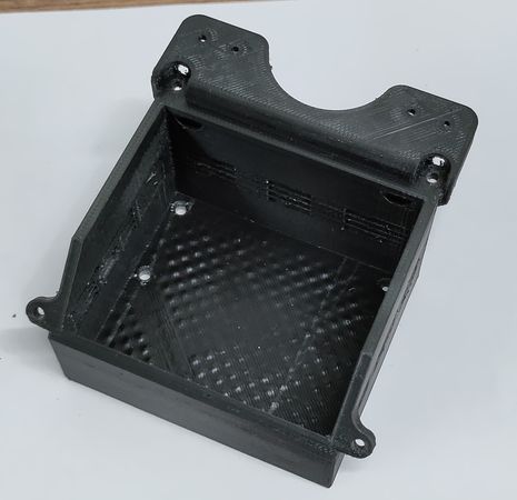
Electronincs housing base
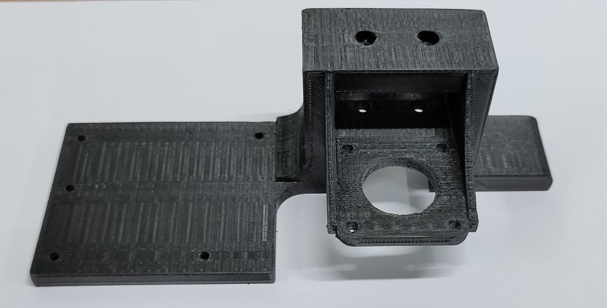
Y axis aluminium extrusion platform (for extreme end position)
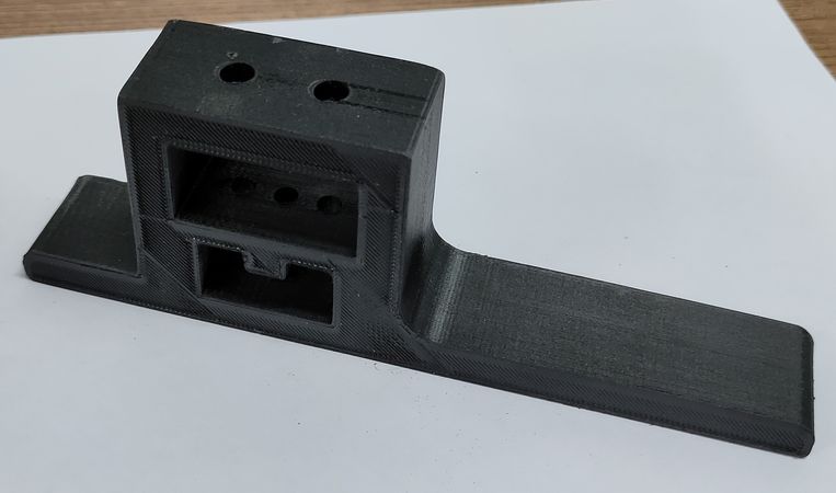
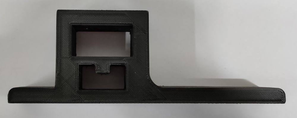
Y axis aluminium extrusion platform (near home position)
X axis aluminium extrusion platform for Vslot wheels (for extreme end position)
Female dovetail part for hopper(supposed to be mounted on X axis Vslot wheel assembly plate)
Locking part for mounting two ends of open loop timing belt (Y axis)
Locking part for mounting two ends of open loop timing belt (X axis)
Three linkage for the spoke
Mounts for dragchain
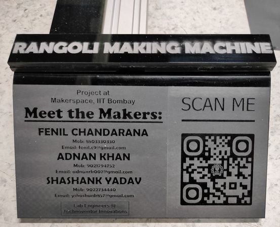
For adding the nameplate onto the machine, we fabricated the part in laser cutting machine,
The acrylic plate onto which the dragchain rests was also fabricated in laser cutting machine.
Click here to go back to the top
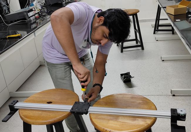
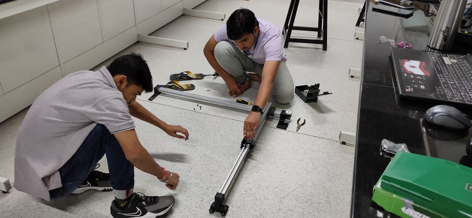
Assembly
Here are all the snapshots of the assembly of the machine with its brief explaination:
When we mounted the Vsolt assembly wheel plate onto the X and Y axis aluminium extrusion,
it turned out that the distance between the wheel was more than required so we
couldn't mount the X and Y axis Vslot wheel assembly plate onto the aluminium extrusions,
for figuring out the required distance between two Vslot wheels, we fabricated the plate in laser cutting machine for quick results,
after few trials and errors we figured out the optimum distance required for both Vslot assembly wheel plate on X and Y axis aluminium extusion,
Mounting the platforms and Vslot wheels assembly plate onto the X and Y axis aluminium extrusions,

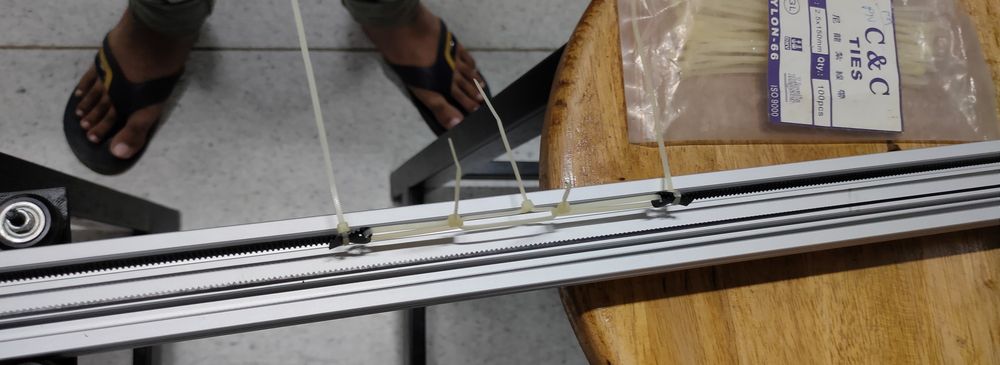
Mounted the stepper motor along with its housing and idler pulley on X and Y axis aluminium extrusion and the open loop timing belt we had
earlier was of short length so we designed and printed a joint to lock both end of open loop timing belt,
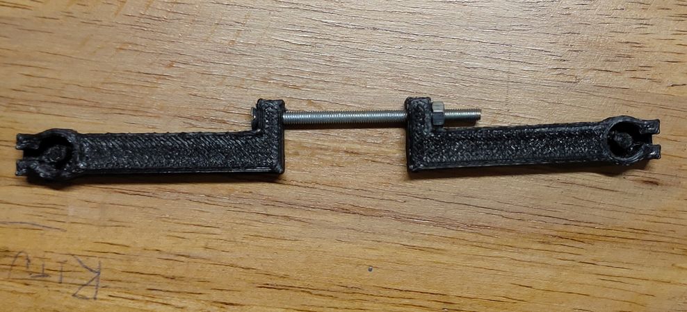
it didn't work so we came up with theh idea of using zip ties instead,
That was just the temporary solution, we late bought longer timing belt and the locking part was enough to mount the ends of open loop
timing belt,
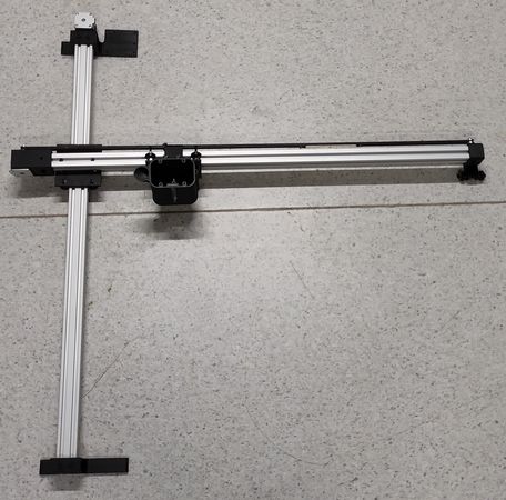
Mounted the female dovetail slot plate onto the X axis Vslot wheel assembly plate and mouted hopper with the female dovetail slot plate and our
machine was ready to actuate manually,
we put a weight of approx. 1Kg on the extreme end of X axis aluminium extrusion to get an idea if there will be anu issue if we fill the hopper
with 1KG color,
mounted dragchain and routed the wires of steper motors, servo motor and vibration module inside the dragchain,
Mounted the housing for the electronics on the Y axis platform, had to enlarge the holes for it
mounted the electronic components like Arduino UNO, CNC shield, buck convertter, fan, DC power jack and SPST switch inside its housing and did
the connections and soldering of all the components.
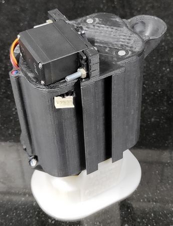
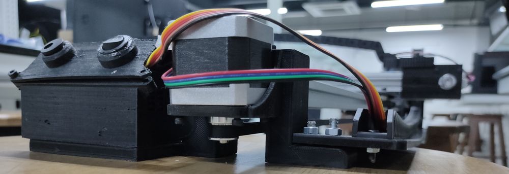
Mounted vibration motor & servo motor and soldered & routed the wires on the hopper,
connected the spoke with the three linkage and the three linkage with the servo motor,
mounted the hopper onto the female dovetail plate and connected the JST connector of the machine with the hopper,
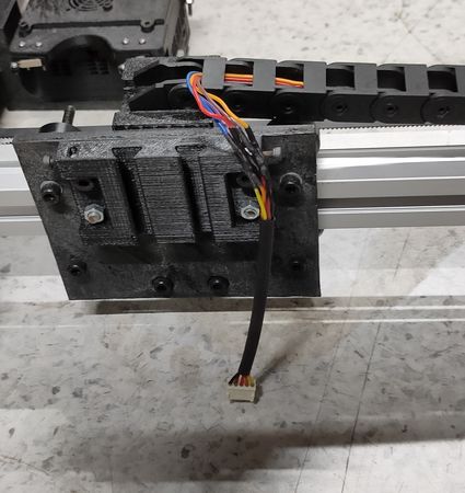
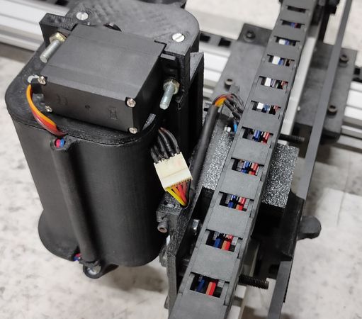
The 5 pin female JST connector from the hopper is conneted with 5 pin female JST connector of the mahcine. 3 pin are for the servo motor and 2
pin are for the vibration motor. The JST connetor's wire along with the stepper motor wire are being connected to the UNO and CNC shield and the
routing is done through the dragchain
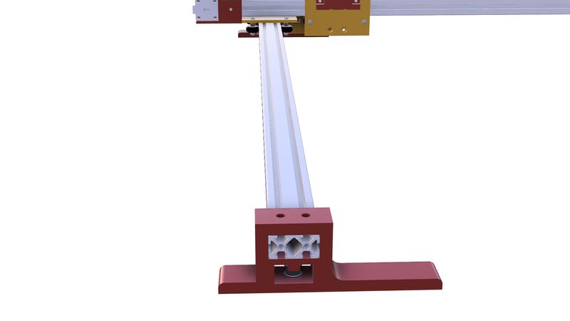
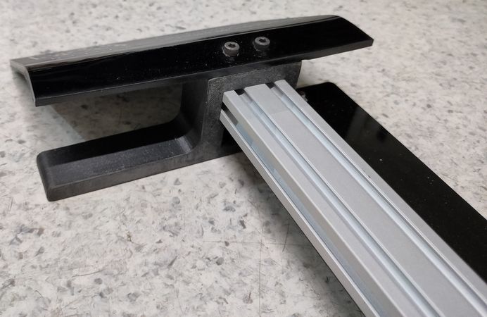
Lastly, bent the nameplate for the machine by heating it and mounting onto the platorm of Y axis. We had not given the provision of mounting
the nameplate while designing, but fortunately there were provision of 2 bolts that locks the platform and aluminium extrusion so we used that,
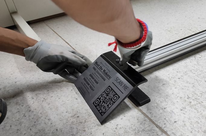
and mounted one more plate that press-fits on the bolts,
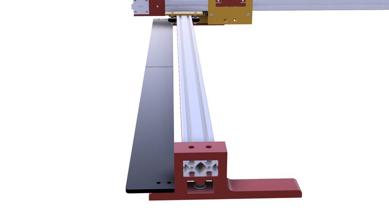
mounted a plate on the Y axis to support the dragchain so it doesn't hang when shifting the mahcine,
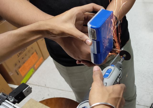
For mounting every mating part, we used M3 and M5 bolts. For some parts we used standard 1" and 2" length, but for most of the mounting
we had to cut the bolts for the desired length,
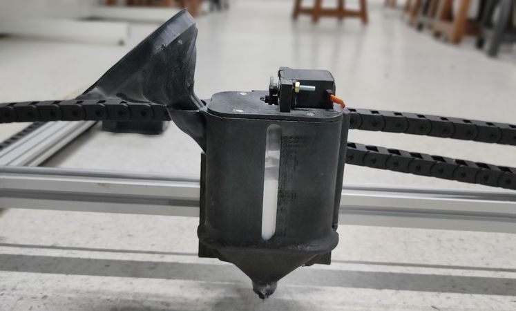
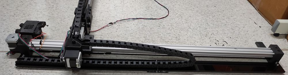
Some final heroshots of the mahcine,


Click here to go back to the top
Electronics and connection
For the electronics components following components are used:
CNC shield is connected onto the Arduino UNO
Stepper motor for the X and Y axis is connected to the CNC shield and the wire goes through the dragchain.
Limit switch, fan, Buck converter, DC power jack and SPST swith are mounted inside or onto the housing of the electronics so these components are directly connected to the CNC shield without routing the wires through drag chin.
From the CNC shield to the X axis Vslot wheel plate(or the plate where the hopper is mounted) 5 wires are routed through dragchain. These 5 wires are of 5V+ & 5V- (for vibration module) 7V+ 7V- & Signal pin (for servo). These 5 wires are connected to the female JST connector
The servo motor and both the vibration motor is mounted onto the hopper and its wire is routed through the in-built tunnel onto the hopper. 3 wire of servo motor 7V+ 7V- & Signal pin and 2 pin of vibration motor 5V+ & 5V- is connected to the male JST connector,
Now when we mount the hopper onto the X axis Vslot wheel assembly plate, just connect the JST connector of hopper and JST connector of machine and so the servo motor and vibration motor will be connected to the CNC shield,
Here is the connection diagram of the electronic components of the machine,
RMM schematic
click here to view the connection diagram in better quality
Click here to go back to the top
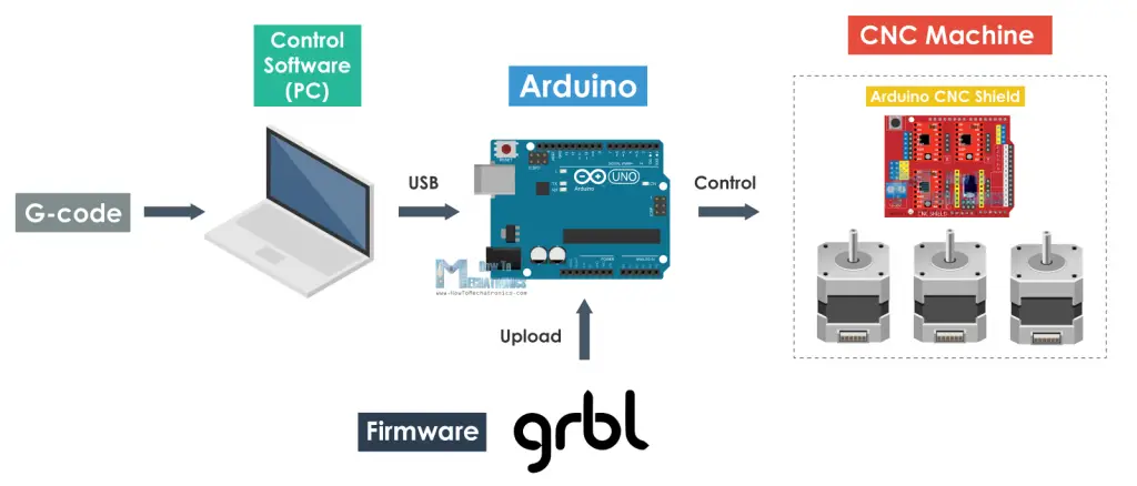
Firmware and software
Since our Rangoli making machine is made of stepper motors, motor driver(CNC shield) and Microcontroller(UNO) we need a g-code(Geometric code
which is a set of command for the stepper motor to rotate) for the machine to actuate.
Now we need a software which can generate gcode, not only for the X and Y axis stepper motor, but also for the servo motor,
out of an image which we want to make the rangoli of. We are using servo
motor so that the it can stop the color flow on the travel path where there is not need to fil the color.
There is an open-source software called Inkscape, which, after adding some extensions, can generate a g-code. There are several versions of
Inkscape released
however the one which worked for us is
Inkscape v0.48
(Links for downloading necesary files mentioned in at the end of the section. Details regarding how to generate g-code & use the mentioned softwares
is given here)
Once you have the g-code, you need to send it to the machine through the UNO. If you directly upload the gcode in the UNO, the sketch won't
compile because the UNO doesn't understand the gcode. For UNO to understand that $H is the command for homing the mahcine and what set of code
should be executed for the stepper motor to rotate until it hits the limit switches, you need a firmware for the UNO to interpret the gcode commands.
You need to upload that firnware
in the UNO and then through a different software you need to serially send the gcode commands to the UNO . This image pretty much sums up
what I am trying to say,
There are several open-soruce firware availabe for 2 axis machines. In some firmware were couldn't home the mahcine while in some firmware we couldn't
actuate the servo motor. Finally we found a firmware called
mi-grbl
which, after slight modifications, was able to home the machine as well as actuate the servo motor with the g-code generated from inkscape.
For our Rangoli making machine we needed a homing sequence. We wanted the machine to home Y axis first and then X axis everytime home command
is given. By default, mi-grbl homes the X and Y axis of the mahcine simultaneously. To change the homing sequence change a line of code, in
line 78,
in grbl-mi\config.h file from,
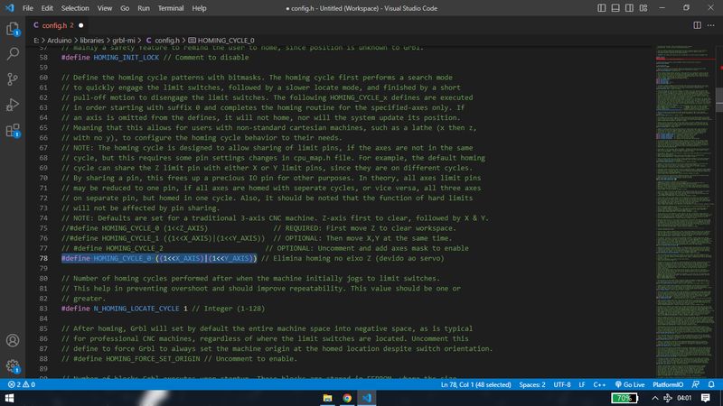
to,

Now that we have firmware uploaded in the UNO and g-code ready, we need a software which can send the g-code serially in the UNO. There are
several open source g-code sender available, however the one that worked for us was
Universal G-code Sender
UGS has released multiple verison of the software and not all the software works with the mi-grbl firmware. The
Nightly build version for Windows 64-bit
worked well for us.
Inkscape v0.48:
https://inkscape.org/release/inkscape-0.48/?latest=1
GRBL:
https://github.com/gnea/grbl
Universal G-code sender(UGS):
https://github.com/winder/Universal-G-Code-Sender
Below it the google drive link for the necessary firmware, software and UGS setting file I used,
https://drive.google.com/drive/folders/1f9b_PlkROXwpoVHQT0LP70XbvwG7teAF?usp=sharing
Click here to go back to the top
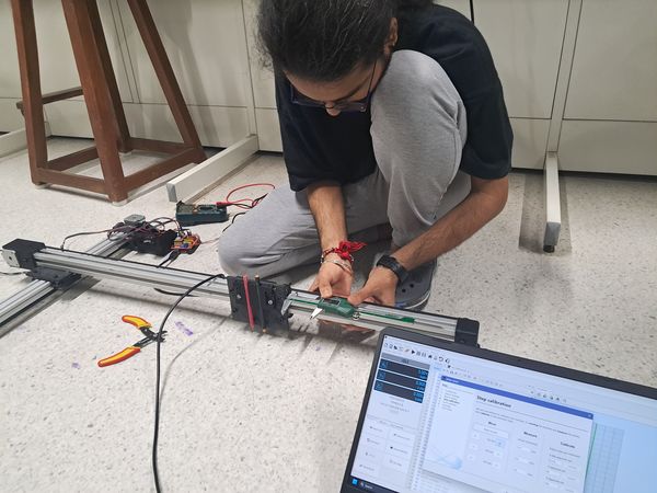
Initial test run
After the mechanical and electronics assembly was done, after the firmware was uploaded, we had to clibrate and setup the machine and do
some test runs
before finally making the rangoli.
Setting up the mahine started with calinrating the steps in UGS. Calibrating steps means when the command to move 100mm is given, the
machine should move 100mm, and not this,
To calirate we had to mention the distance given in the input and the actual distance travelled by the machine in the UGS,
If there is any error in the steps calibration, this is how the rangoli will look like after it is made,
Next was to enable the homing,
Next was actuating servo motor and do a dry run,
Some fail runs,
Glimpse of the first rangoli that the mahcine made,
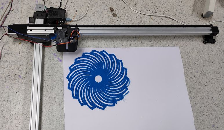
Some more test rangolis,
If you have observed, there were several spots in the rangoli where there were blobs of color because hopper was staying at a spot for some time
while servo hadn't plunged the spoke down. This was however eliminated after changing the firmware and removing the delay from Inkscape
while generating g-code.
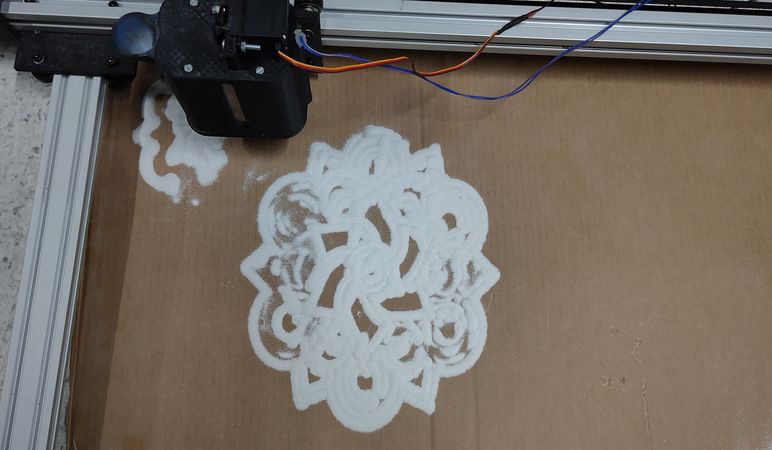
While we were doing multiple trial runs, we speculated that white rangoli color was much finer compared to the blue rangoli color. The logic
is that while making traditional rangoli, white color is used to make the border/boundry of the rangoli and non-white color is used
to fill the space between the border and so the border has to be neat and sharp because of the white color is much finer with smaller grain
compared to non-white color.
Since we wanted to make a sharp and neat rangoli while covering as much detail as possible, we decided on using white rangoli color for
the rangoli making mahcine as a norm. Here are the resuts with the white rangoli color,
We observed that the color was clogging inside the nozzle during making the rangoli. We speculated that the tiny grains of color was
getting stuck on the inside of the nozzle, this finishing of it was not smooth. So we decided onto clearing out the hopper completely
and refilling the color again after making every 2-3 rangolis as a norm and doing that seemed to eliminate the issue of clogging the nozzle.
Click here to go back to the top
Iterations
There were multiple iterations made throughout the developement of the mahcine on mechanical, electronics as well as the software and firmware
end. Here is the brief description of some key modifications made on the machine,
Having 2 part assebly hopper instead of 3 part assembly hopper
Initially we were using hopper which was assembly of 3 parts: lid, container and nozzle,
Since we were using virbation motor which was mounted very close to the tip of the nozzle, making the nozzle detahable means either shift
the vibration motor on the container, which might effect the flow of the color or making the routing of the wires complex if we decide
to keep the vibration module at the same place.
So for the final version the hopper was divided in 2 parts: lid and the container with nozzle at the bottom of the container.
Switching from CNC shielf V4 to CNC shield V3
Earlier we were using CNC shield V4 as it is more compact than the V3. While using V4 we were facing difficulty in micro-stepping so the movement
of the stepper motor was either like this,
or like this,
after switching to CNC shied V3 the movement were like this,
Switching from MG90 servo motor to MG995 servo motor
While using the MG90 serov motor, due to the friction of the color and less torque of the motor, it used to stalled again and again and we had
to switch it with new motor. The below video is the representation of the motor getting stalled. Before filling the color, the spoke used to
penetrate the hole of he nozzle but after filling the color, though it should still penetrate the nozzle, it wasn't able to
Later we switched to bigger motor, MG995 servo motor and after that there was an instance where due to low positioning of the hopper to the
ground, the spoke hit the ground and MG995 bent the spoke but the motor didn't stalled,
Using a larger size vibration motor
Initially we were using a small coin shaped vibration motor,
However, we felt like the vibration motor was not doing much work so we switched to a larger cylinder shaped vibration motor for better
color flow,
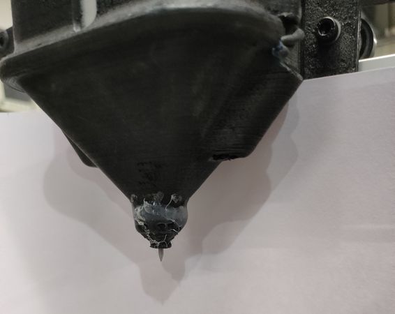
Using a 2mm nozzle instead of 3mm nozzle with a sharp spoke at the tip
While we were using the hopper with detachable nozzle, the size of the hole of that nozzle was 3mm and we were using spoke of approx 2.5mm
diameter with a flat point,
For the final version of the hopper we were using nozzle with 2mm hole and the diameter of the spoke was approx. 1.8mm and the tip of the
spoke was sharp so it can easily penetrate through the color,
we didn't plan to but we had to attach a small nozzle at the end of the hopper because due to some error in 3D printing, the size of the
hole increased.
Using mi-grbl and Inkscape v0.48
We explored multiple Inkscape version, for generating single stroke text g-code, for generating g-code for servo motor, the version
that finally worked for us was v0.48.
We also explored multiple firmwares, some firmware was able to home the machine while not being able to actuate the servo motor while some
firmware was able to actuate the servo motor but not able to home the machine. Finally, mi-grbl was the firmware that worked for us.
modifying the IITB logo
This is the original logo of IIT Bombay,

It was not possible to cover all the minute details of the logo in the rangoli as the width of the line drawn by the rangoli making machine was
about 4mm. To cover details like text, we would have to scale up the logo, which was again not possible. Even after removing just text, this
is how the logo looked like,
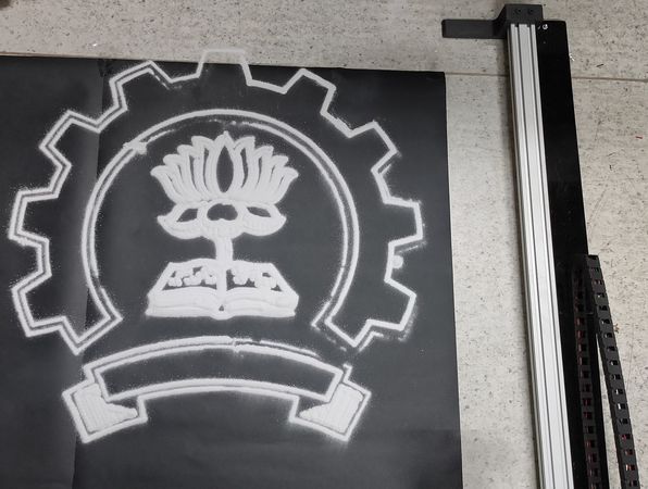
So we edited the logo further so that we can see visible stripes in the ribbon below, on the lotus as well as on the book. Here is what the final
result looked like,
Click here to go back to the top
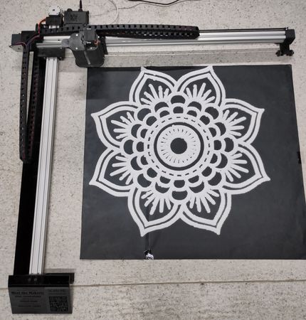
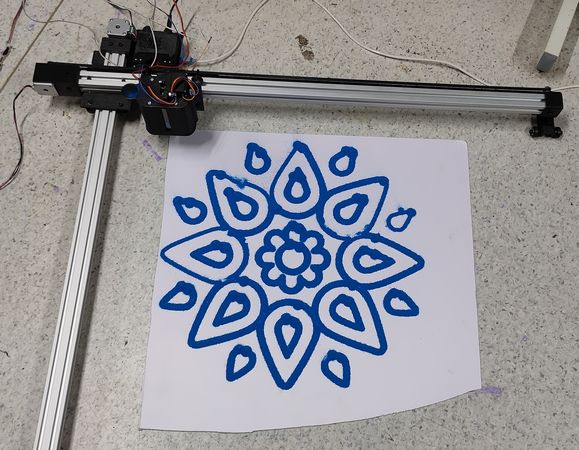
Final results
Here are the final rangolis made by the machine,
Click here to go back to the top
Limitations
There are certain limitations with this machine,
1. This machine can't draw minute details. Since the size of the trace is around 4mm, drawing texts and minute details will very difficult as
you might have to modify the design by enlarging the size of removing the minute details.
2. The machine can draw maximum size of 650 width x 750 height of the rangoli.
3. The maximum caacity of the hopper to fill the rangoli color is 1KG
4. The machine is suitabe for using fine and small grain rangoli color like white color. Using any other color might clog the nozzle.
5. There is no option to resume the design after a power failure or power backup in case of electricity cut-off.
6. This machine can draw only a single color rangoli
7. As we are using an open source software and firmware, there are very few modification we can make in the machine.
Click here to go back to the top
Challenges faced
Some of the challenges we faced in the developement of the machine,
1. Trying multiple firmware and softwares until we found the one which was suitable for our machine.
2. Designing and testing multiple hopper and nozzle sizes before figuring out an optimum design and dimensions for the nozzle along with its
spoke.
3. Switching different electronic components like CNC shield V3 after CNC shield V4 was not working for our purpose,
using MG995 servo motor after multiple MG90 servo motor was stalled, using larger vibration module when the smaller one was not effective.
4. Routing and wires throughout the machine, esspecially the hopper. Routing the wires through the tiny tunnel of the hopper without breking
the thin wire of vibration motor was very difficult.
5. Eliminating rat-holing effect and figuring out how to control the color flow from the hopper did take multiple trial and error.
Click here to go back to the top
Future enhancement
Here is how we can improve the machine,
1. Enhance the machine to accommodate multicolor rangoli designs by either having multiple hopper and using dual nozzle mechanism like
3D printer or using tool changing mechanism like CNC milling machine.
2. Custom firmware and software development so that we can enhance the machine by adding a disply screen with feeding g-code through
micro SD card and having the machine automatically home before the start of every design instead of manually homing it.
3. Making it Modular to accommodate larger rangoli designs.
4. Achieve complete Flow control within the nozzle. Currently we can only control the flow in the form of ON or OFF. However it would be great
to have a thin and slow flow to cover minute detils of the design in rangoli.
5. Adding a microprocessor like Raspberry pi for fetures like resume the operation after power failure, octoprint to control the machine wirelessly.
Click here to go back to the top
Acknowledgement
We would like to express our sincere gratitude to the following:
Makerspace, IIT Bombay: For providing us with the conducive environment and resources necessary for the execution of this project.
The facilities and support at IIT Bombay have been integral to the successful development of our work.
Technoventor Innovations: For their continued support and employment which have been instrumental in the successful execution of
this endeavor.
Professors from Mechanical and Electrical department for their valuable feedback and appreciation.
Special thanks to Prof. Varun Bhalerao and Prof. Abhijeet Majumdar for enabling us to work on this project and his
continuous support throughout.
Thank you All the lab staff for your invaluable support and encouragement throughout the project.
Click here to go back to the top