Brief description about the clock
I came across a video of this clock and when i looked up online, I found the original creator of this clock:
Humans since 1982.
This is how we made our version of the clock.
A glimpse of the final result:
This is a 24-hour format clock which is a fusion of electronics and mechanics. The clock is made of 24 pair of handles, operated by 48 stepper motors. So one steper motor is assigned for evey handle.
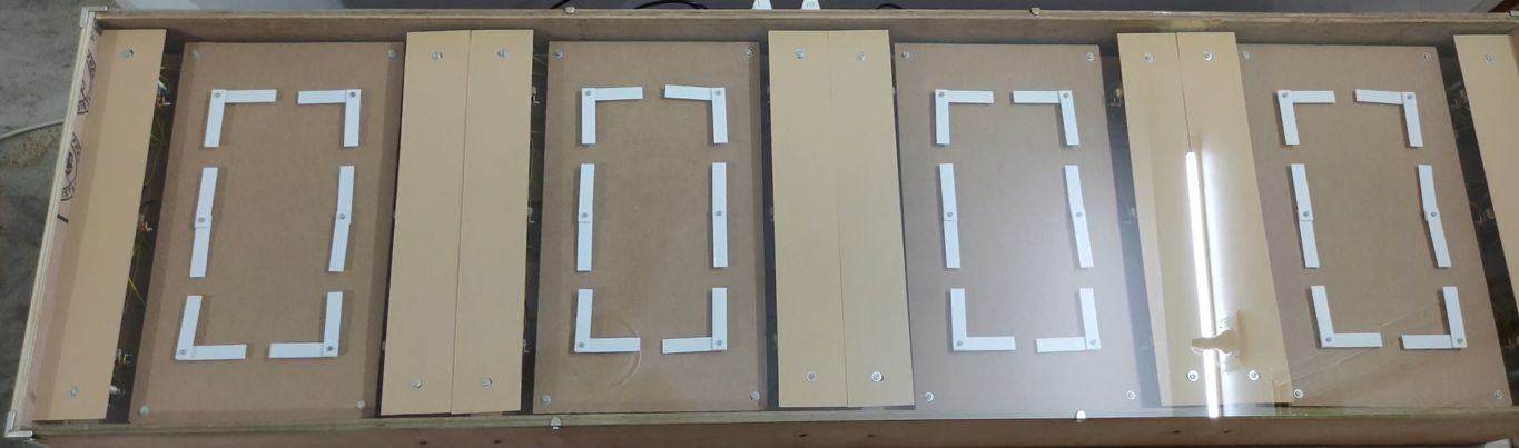
The clock is equally divided into four set, each set representing a digit,
each set had 12 stepper motor, 12 stepper motor driver, 6 infrared sensor, 6 printed circuit board with resistors for infrared sensor, a real-time clock module, a microcontroller and a power supply unit. Every set of the clock operartes on its own and there is no connection/communication between the sets.
Click here to go back to the top
List of all the component
Here are all the electronics components used for the clock,
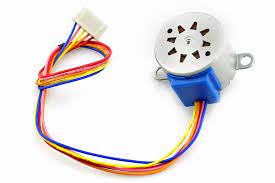
stepper motor: 28BYJ-48 stepper motor. Quantity: 48
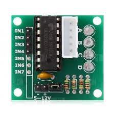
stepper motor driver: ULN2003 stepper motor driver. Quantuty: 48
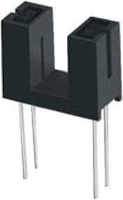
infrared sensor: ITR9608 sensor. Quantity: 24
real-time clock module: DS3231 and ZS-042. Quantity: 4

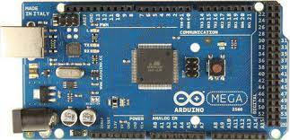
microcontroller: arduino mega 2560. Quantity: 4
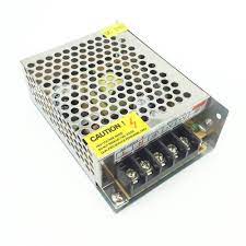
power supply: 5V5A SMPS. Quantity: 4
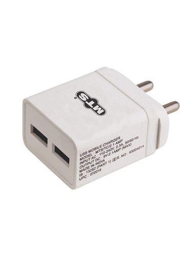
power supply: 5V2.1A dual port USB adapter. Quantity: 2
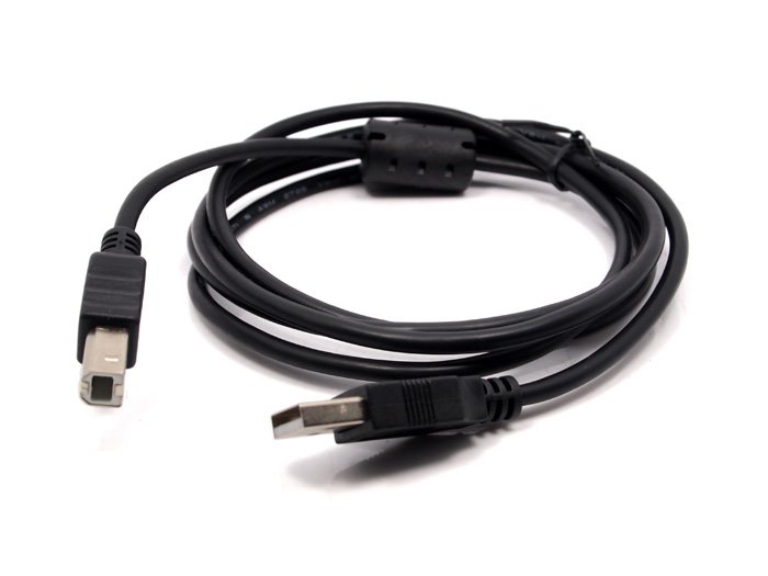
USB cable: USB type A to USB type B cable, 1 meter length. Quantity: 4
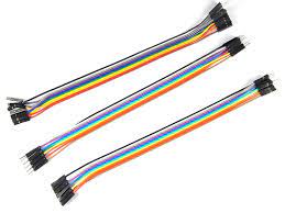
jumper wire: Male to female jumper wires. Quantity: many
Connection
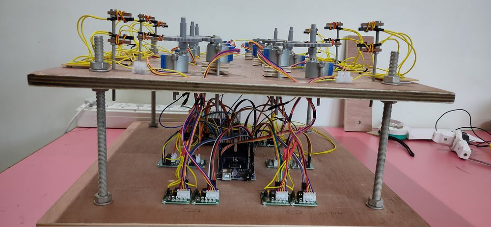
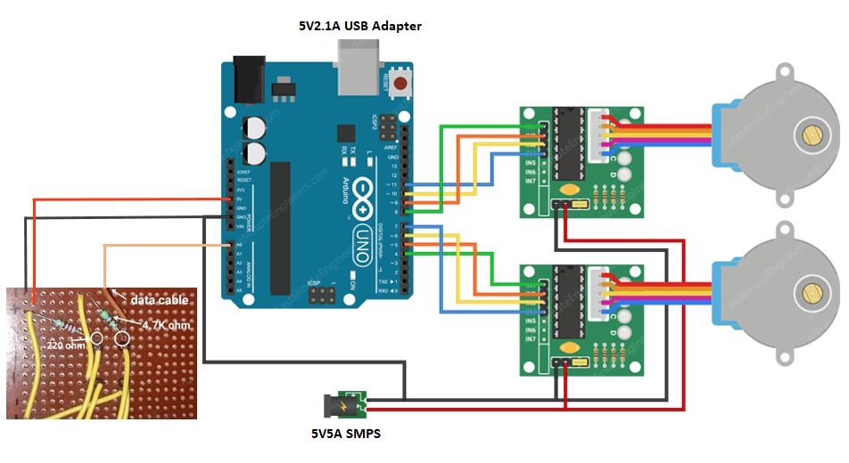
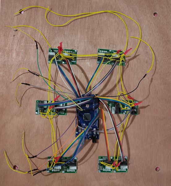
Here is the connection of stepper motor, driver, PCB for ITR9608 sensor with the arduino mega along with the power supply,
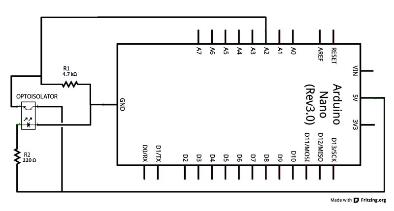
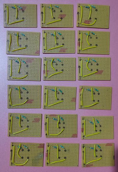
here is the schematic of the PCB for the ITR9608 sensor,
same manner of connection is used for 12 stepper motor, 12 stepper motor driver, 6 PCB for ITR9608 sensor with ITR9608 sensor, arduino mega and
power supply.
here is the connection of the ITR9608 sensor with the PCB,

all the VCC of the PCB for ITR9608 were attached to a common VCC and all the GND of the PCB for ITR9608 were attached to common GND and the common
VCC and common GND were connected to 5V and GND of Arduino mega respectively.
common GND and VCC of the stepper motor driver is connected to 5V5A SMPS. common GND and VCC of the PCB for ITR9608 is connected to the arduino
mega and the arduino mega is powered by 5V2.1A USB adapter.
Assembly during trial and error
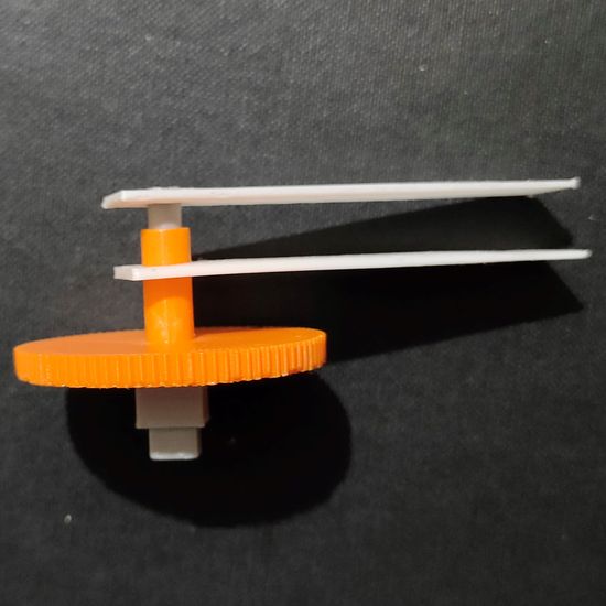
All the handles are attached to the gears and the gears are attached to the shaft of the motor. Handles and gears are 3D printed. The 3D printed
parts consist of,
2 handles: handle cylinder and handle cone
a cylinder divided in two parts: top cylinder and bottom cylinder
cone gear with 88 teetth
spur gear with 44 teeth
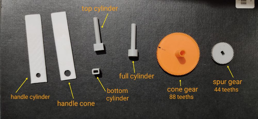
(the design of cone gear was changed in the final assembly)
Here is how the gears and handles are attached,
the bottom cylinder is suppose to be inserted into the top cylinder,
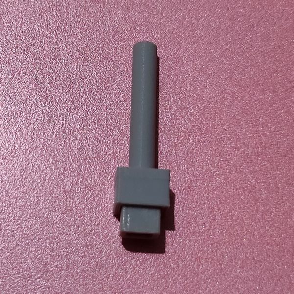
attach the spur gear onto one motor,
attach the whole cylinder onto other motor,
slide/mount the cone gear onto the whole cylinder,
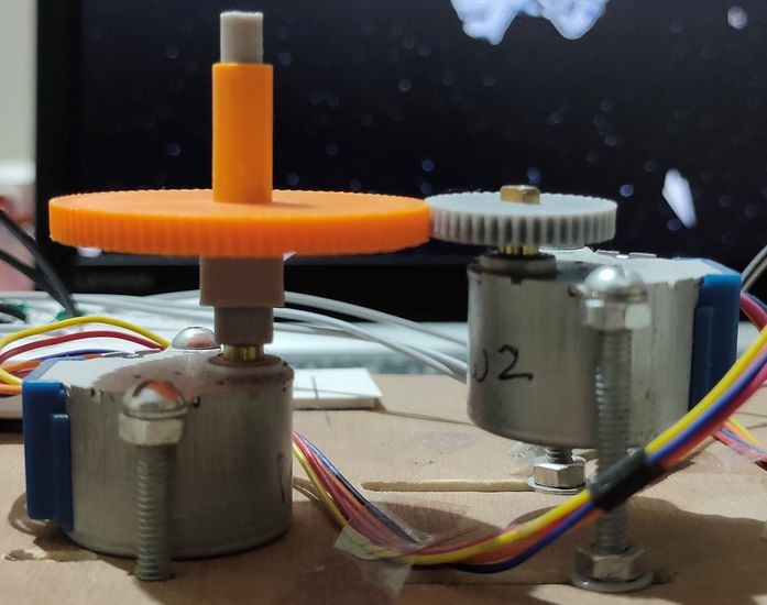
attach handle cone to the cone gear and attach handle cylinder onto the cylinder,
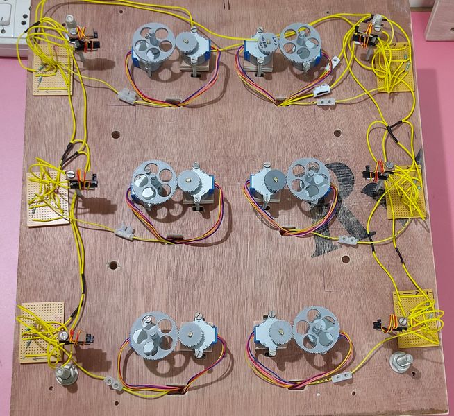
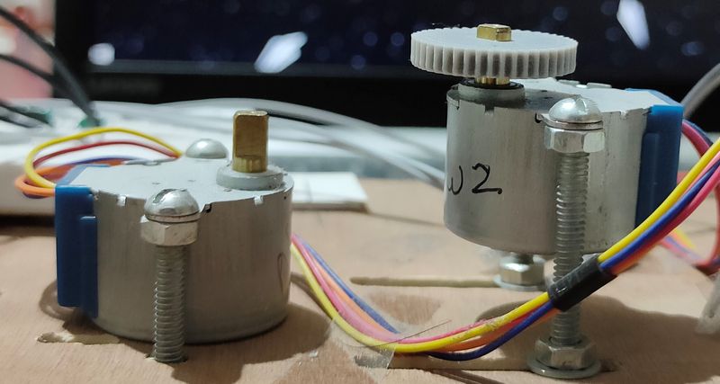
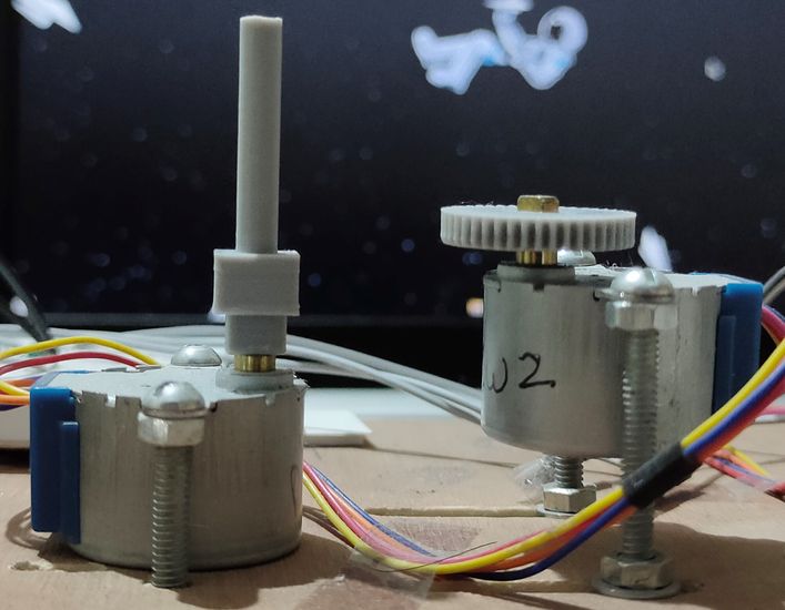
the motor with cylinder, cone gear and handles are mounted ONTO the surface while the motor with the spur gear is mounted ABOVE the surface
where the teeths of the spur gear and cone gear is properly meshed. This is one pair of handles. There are 24 pair of handles with the same
arrangement. (The below image is the temporary arrangement while testing, arrangement for the pair of motors on the right was changed in the
final assembly)
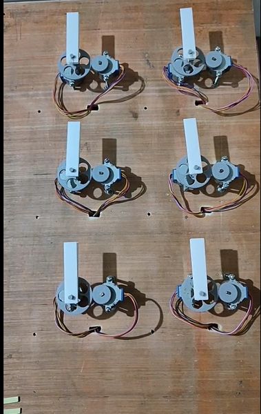
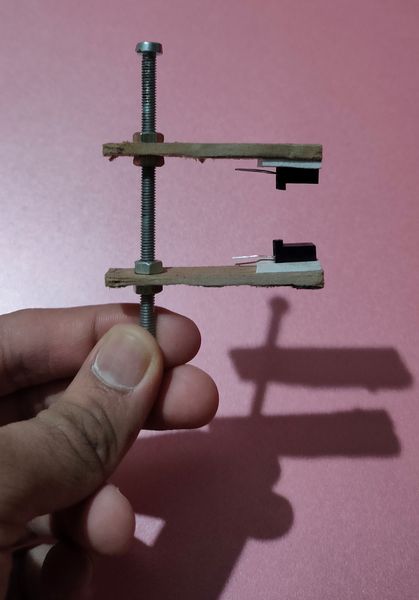
The handles are suppose to pass through the ITR9608 sensor and the gap between the transmitter and receiver is small so i split the sensor in
two and attached them onto the bolt like this, (the below image was just a temporary arrangement, the length of MDF sheet and the gap and position
of the sensor is different in the final assembly)
Final assembly
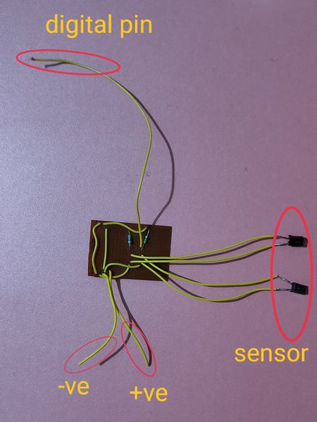
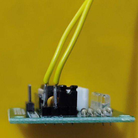
I prepared the printed circuit board for the ITR9608 sensors by attaching 4.7Kohm and 220ohms resistors and wiring them. I gave the provision for
7 wires.
4 wires were suppose to be attached to the ITR9608 sensor. 2 wire were suppose to be attached to the commmon GND and VCC. 1 wire was suppose
to be connected to the digital pin of the arduino mega.
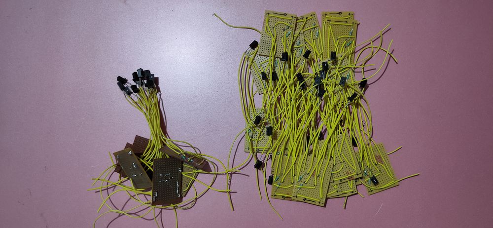
Connected ITR9608 sensors to the PCB. Attached a wire connector to the wire which was suppose to be attached to the digital pin of arduino mega.
Connected all the GND and VCC of the PCB and then attached a common wire that act as common GND and VCC with wire connector at the end of it.
atatched the jumper wire to all the wire connectors,
mounted PCB with ITR9608 sensor attached onto the top layer of the clock,
then mounted the ITR9608 sensor onto the bolt,
also mounted the stepper motor with cylinder, spur gear and cone gear attached.
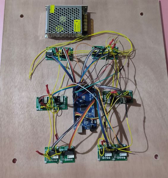
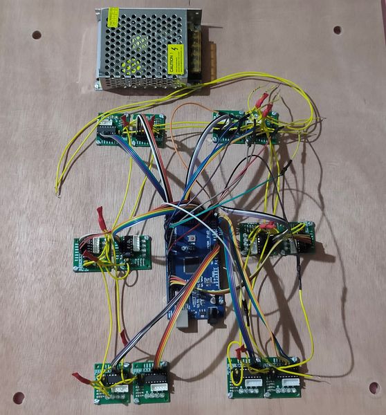
for the bottom layer of the clock, i first mounted stepper motor driver and arduino mega,
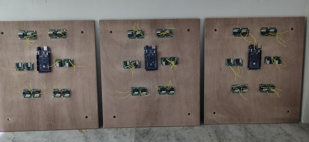
i then connected all the GND and VCC of the driver and attached a common GND and VCC which is to be attached to the SMPS. One of the ground
is connected to the GND of arduino mega.
connected IN1,2,3,4 of the driver with the digital pin of the arduino mega,
attached the SMPS,
mounted the top layer onto the bottom layer. Connected the stepper motor with the driver, connected the data pin of the PCB for ITR9608 sensor
with the digital pin of the arduino mega, connected the common GND and VCC of the PCB for ITR9608 sensor with the GND and 5V of the
arduino mega respectively and connected the common GND and VCC of the driver with the SMPS.
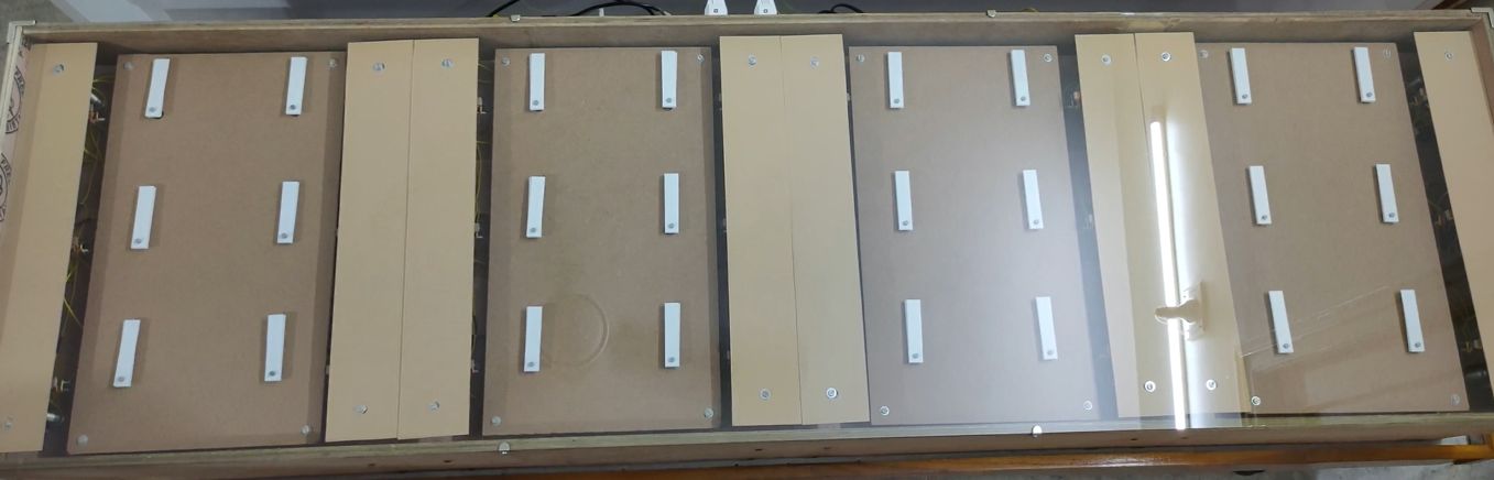
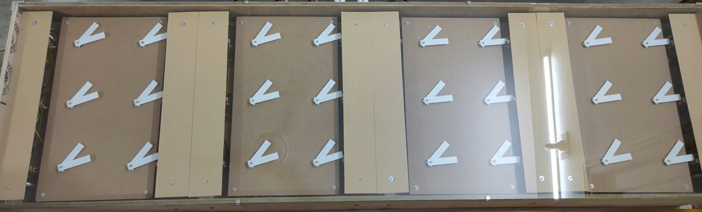
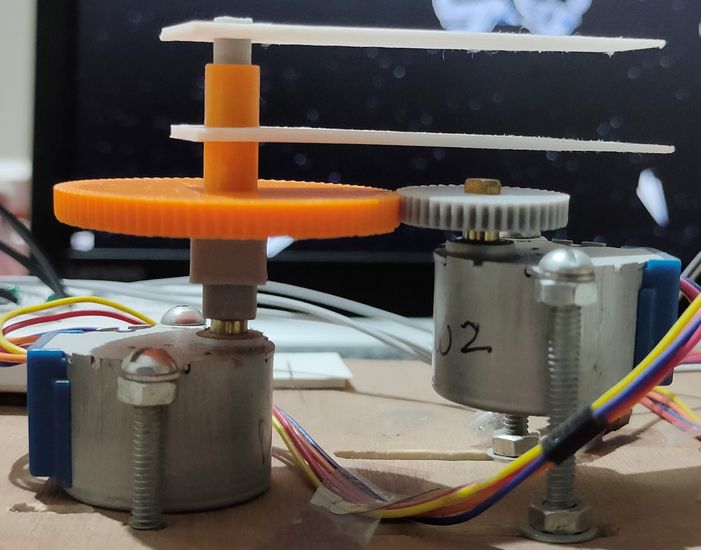
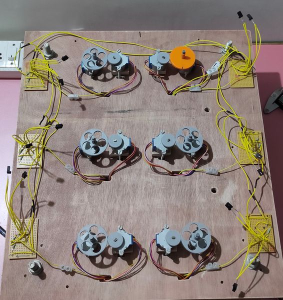
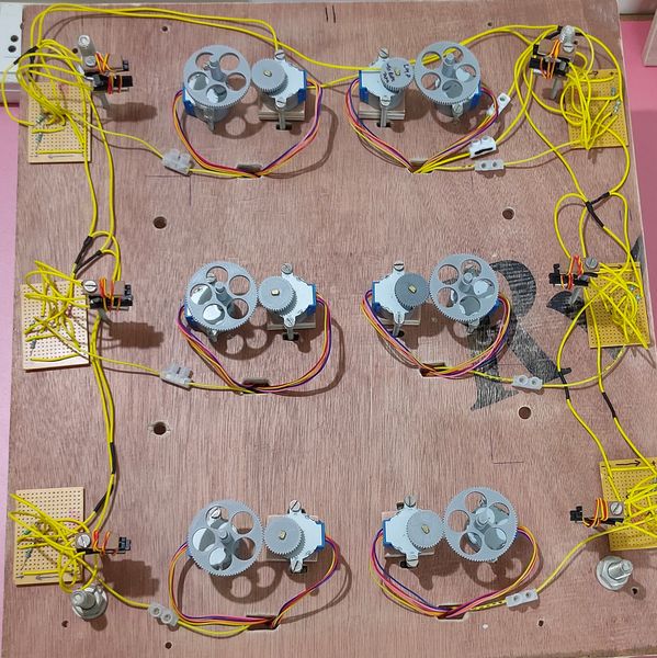
mounted a third layer onto the cone gear to cover all the motors,
[[[img 930]]]
and then mounted the handle cone and handle cylinder,
[[[img 813]]]
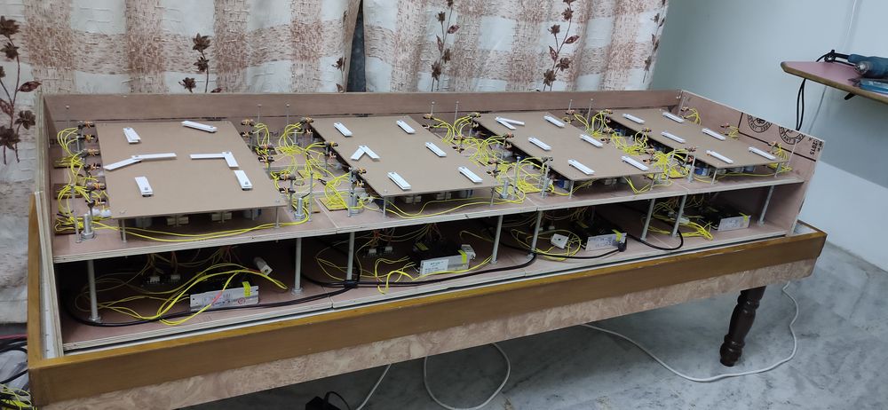
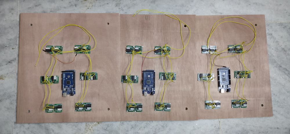
attacehd all 4 sets together and connected the USB cable to the arduino mega and connected wire with plug for the input power supply to the SMPS,
mounted another third layer to cover the sensors,
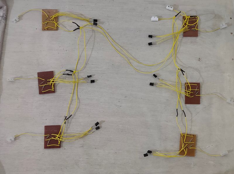
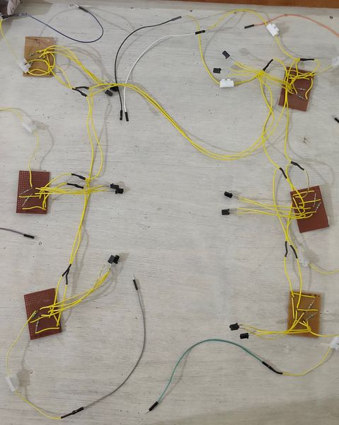
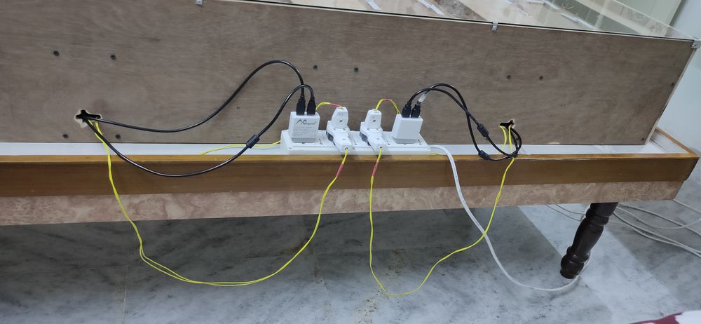
after closing the clock with the back panel, this was the wiring for the AC input power supply. The two adapters on the end supply the power
for arduino mega and the four plug supply the power for the SMPS,
Programming
Two sketches needs to be uploaded to the arduino mega for the clock to run efficiently,
- eeprom_write 3(3)
- sensormegadigit_7 (2)
This sketch,
1. sets the time manually.
2. assign the digit type, whether it is H, h, M or m.
In the time 23:46 2 is H, 3 is h, 4 is M and 6 is m. Since the clock is divided into 4 sets with no connection or communication between them,
you have to define the digit type whether it is H,h,M or m. So in the clock, the fourth set or the set on the extreme right is m, the set beside
m or the third set is M and the first set or the set on the extreme left is H.
The time needs to be set manually. This sketch needs to be uploaded to the arduino with RTC connected. After uploading, open the serial monitor
and it will ask to enter the date, which i don't think is necessary, just hit enter and it will not update the date. Then you need to enter the
time, hours and minutes like 23:46.
After entering the time if will ask to define the digit type: H, h, M, m, S or s. Set the digit type accordingly. This sketch configures the
RTC module by defining the time and digit type so it is required to upload this sketch first for all 4 sets/arduino mega.
sensormegadigit_7 (2)
In this sketch, it is required to first set the values for the sensor.h file/function. The values defince the number of degrees the motor needs to
rotate for the handle to reach from the ITR9608 sensor to the home position/U. For calculating the degrees, use cny70stepper_test_2_start_1
sketch can be used.
what sensormegadigit_7 (2)> sketch does is that it will read the state of the RTC module: the digit type and the time. Let say in the
eeprom_write 3(3) sketch
i set the time 23:46 and set the digit type as M. So when the sensormegadigit_7 (2) sketch is uplaoded, the arduino mega will only
focus on the digit on the M place. Arduino will only update the state of the handle when the M digit in the RTC module gets updated, so arduio
will not change the
state of the clock when the time updates from 23:46 to 23:47, it will not change the state when the time updates from 23:47 to 23:48 and
23:48 to 23:49, it will only
change the state when the time updates to 23:50 since the digit on the M place is updated from 4 to 5.
After uplaoding this sketch, first all the handles will rotate and placed at home position/U. Then according to the time in RTC module, motor will
rotate to form the digit. Whenever the time in RTC will update, the state of the clock will be updated too, considering the digit type.
Stein Gulbrandsen helped me with the complete programming of the clock, from rotating 2 motors
simultaneously till the complete configuration of the clock with the two sketches mentioned above. Without his selfless help, this project would
never have been possible.
Stein's email address: harelabb@lyse.net
Final result
Here are the final reslts.