Rangoli Making Machine
A one of a kind, 2-Axis CNC Rangoli Making Machine with a novel color-flow control mechanism
About the project: This project was developed with the support of Design and Making lab(Makerspace), IIT Bombay
by the Lab engineers:
Adnan Khan,
Shashank Yadav and
Fenil Chandarana. This is a 2-Axis Making Machine
with Cartesian mechanism and a uniquie color-flow control mechanism. The machine will be able to make a rangoli of 650mmx750mm size.
We have used open source software and firmware to run the machine and the components used in the machine are also open source.
For the hopper(container having color), mating part for the assembly of the machine and housing of all the electronic components,
we have fabricated the parts in 3D printing machine and for the linkage which controls the flow of the color, the base for chainmail and
the color level indicator, we have fabricated the parts in laser cutter.
For more details visit the webpage:
https://fenilchandarana.com/rangoli-making-machine.html
DigiAnalog Clock
A digital clock that looks like it is made of multiple analog clocks,
About the project:
This clock is the fusion of electronics and mechanics. It is made of multiple stepper motors, motor drivers, microontroller etc. From
brinstorming till the completion of the project, I invested two and a half years. For more details visit the
webpage
gpioX
A device that lets you connect sensors without breadboards or jumper wires,
About the project:
Want to interface an ultrasonic sensor?
Normally, you'd grab a breadboard and jumper wires and manually route the sensor’s pins to the microcontroller. This device removes that entire step. It provides
universal GPIO pins where any pin can be configured in software to act as 3.3 V power, GND, or a signal pin. Sensors can be connected anywhere on the board, and their
pin functions are defined digitally instead of physically. This simplifies wiring, reduces setup friction, and lets users focus on understanding sensor
behavior rather than pin layouts.
For more details visit the webpage:
https://fenilchandarana.com/gpiox.html
Eleclopedia
A chatbot that provides tried and tested wiring diagrams, codes, libraries and other information for
your electronic components,
About the project:
Using an electronic component sounds simple until you actually try it. You need a wiring diagram, the right code, a compatible library, and the exact board version
it runs on. Finding all of this online is a rabbit hole, and asking AI is constant trial and error. Eleclopedia is a chatbot that understands what you need and
instantly pulls the right tried and tested file for your component from its database.
For live demo visit
https://eleclopedia.fenilchandarana.com/
openCV + LED Matrix
Replicate the LED pattern with hand gestures,
About the project:
An openCV python script that detects the hand movement and gestures by tracing endpoints and skeleton lines accross your hands. A gird of pixels as an overlay that
simulated turning on LEDs as the hands traces over the pixels. The python script then sends the data of the state of all 32x32 LEDs to the esp32 and accordingly the
esp32 will turn on the MAX7219 LED matrix.
For more details visit the webpage:
https://github.com/fenilchandarana/openCV/tree/main/hand_gesture_ledmatrix
Autonomous Musical Keyboard
A bot that plays the keyboard based on the instructions fed to the microcontroller,
About the project:
This project was developed during my time at FLAME University
and serves solely as a demonstration of my work.
All rights to the project are owned by the university.
Click here to go back to the top
Speech to Image print
A device prints an image based on the speech prompt you give,
About the project:
This project was developed during my time at FLAME University
and serves solely as a demonstration of my work.
All rights to the project are owned by the university.
Click here to go back to the top
Chowkidaar
A device that grants the access to use the machine to only authorized person, keeps record
of when the machine was turned on and off and automatically shuts down the machine if it is in idle state for too long,
About the project:
This is basically
The Auto shutdown device,
but on steroids! Along with the Auto shutdown feature which shuts down the machine if it is in the idle state for a long time, this device has
additional features that controls the access of the machine and allows only authorized people with issued RFID card to turn on the machine. The
device also records the information about who accessed the machine, at what time and till what time. You have the flexibility to alter the
authorization access wirelessly at any time.
For more information, visit the webpage
Click here to go back to the top
Ghatam Ghotala
A fusion of sculpture and electronics where I tried to integrate tactile sound of Ghatam
with light and hand motion with electronic sound
About the project:
This project was developed during my time at FLAME University
and serves solely as a demonstration of my work.
All rights to the project are owned by the university.
Click here to go back to the top
Quadcopter
A toy that can fly, kind of,
About the project:
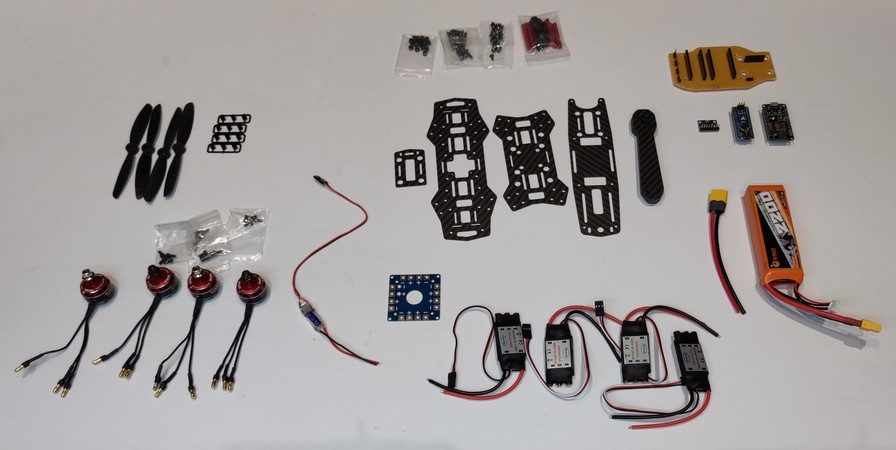
Building a drone was in my bucket list since a very long time. With the support of
Shashank Yadav and
Dip Ghodmare
I was finaly able to build one.
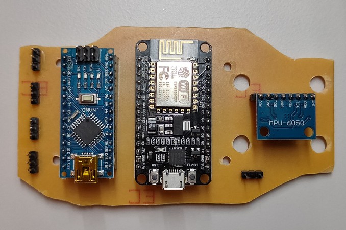
This drone is controlled with the help of a mobile app called RemoteXY. And the drone is built with ESP8266 and Arduino nano. The ESP8266 will
communiate with the RemoteXY app and take the input and send the output to the Arduino nano. The nano will take the input from ESP8266 and drive
the ESCs accordingly. The drone also has a MPU6050 gyroscope for stabilization,
I then designed a PCB with joysticks and esp32 as a microcontroller which would work as a replacement for the remote XY app.
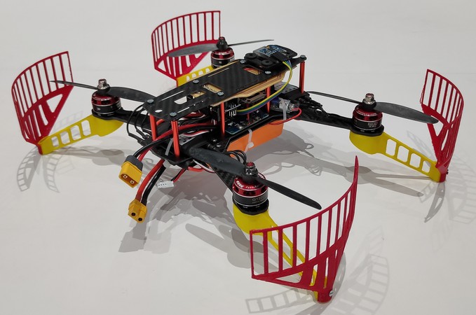
With the remote I could calibate the joysticks & later use it to fly the drone, arm/disarm the remote
and see the status of the components of the remote on the OLED display,

I then change the propeller and landing gear which were much sturdier,

Click here to go back to the top
RC Car
A toy that runs on the ground,
About the project:
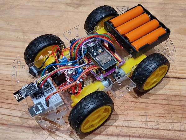
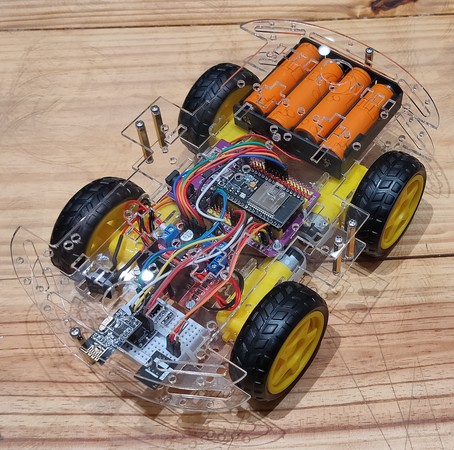
For the RC car, I used ESP32, since it has in built bluetooth and WIFI, along with nrf Transceiver and IR remote sensor, so it can be controlled
with multiple protocols. For the motors, I used BO motors and 4x 3.7V rechargable batteries. I bought readymade chassis kit that comes with
acrylic chassis and standoff spacers,
Here is the connection diagram for RC car,
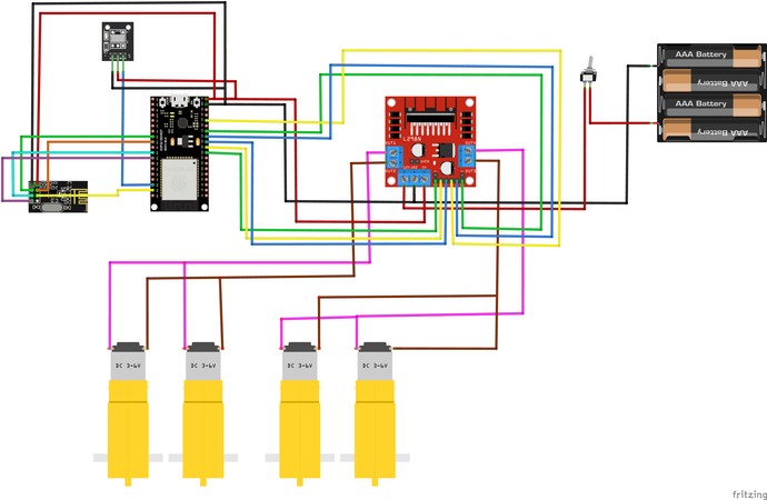
You can download the code used for RC car(receiver) from
here
Now for the remote, I used joystick module, arduino nano and nrf Transceiver,
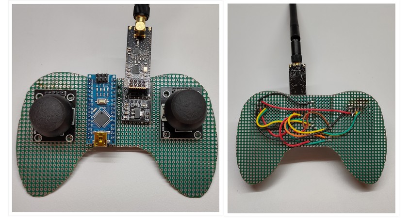
I then designed a PCB with the same components,

Here is the connection diagram for the RC remote,
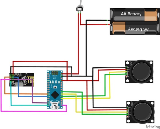
You can download the code used for RC remote(transmitter) from
here
RC car controlled with mobile app
Since the esp32 had inbuilt bluetooth and wifi capabilities, I thought to use a pre-built mobile app to control
the RC car
You can download the Dabble app from playstore:
https://play.google.com/store/apps/details?id=io.dabbleapp&hl=en_IN
You can download the code used for the RC car when controlled with Dabble app from
here
Later exploration of uring a Flysky FS-i6 remote to control the RC car with Mecanum wheels:
Click here to go back to the top
Auto shutdown - Non Invasive
A device that automatically shuts down the 3D printer after the printing job is
done. However, unlike the one mentioned above, this is a non-invasive one. Meaning, this is a simply plug-and-play
device and you don't need to reconnect the connections inside PSU.
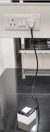
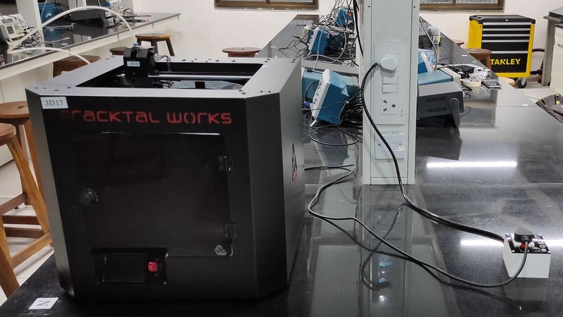
Here is the working of the device in Julia advanced 3D printer,
About the project: This too is a PCB designing project consisting of designing and fabricating a device which can detect when the
printing job is done and after the detection it will shutdown the 3D printer.
While I was working on the invasive version of the Auto
shutdown device, a colleague
and mentor of mine,
Tushar Bhole
suggested to make the device where we don't need to reconnect anything inside the PSU of
the printer and to make it like an extension board/spike guard, which can be directly connected to the mains.
So I modified the design and used different components for the device.
It is suposed to be connected
in series between the mains power supply and the 3D printer. So the installation is simple, connect the
device into your mains power supply and connect the 3D printer into the device,
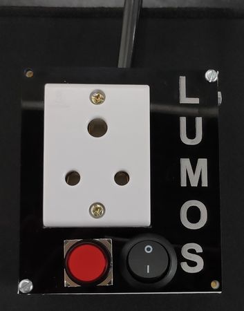
The device has the option to enable or
disable the Auto shutdown function, it will only shut down the printer automatically if you have turned on the
device's SPST switch.
Once installed, keep the switch on the PSU of the printer always on and in order to turn on printer, press the device's push
button and
in order to manually shutdown the printer, turn off the mains power supply.
This project was developed with the help of Design and Making lab and Microfactory (Makerspace) IIT Bombay. Microfactory
provided the micro-milling machine to mill the intital test PCBs and Design and Making lab provided the 3D printing
machine to test those milled
PCBs.
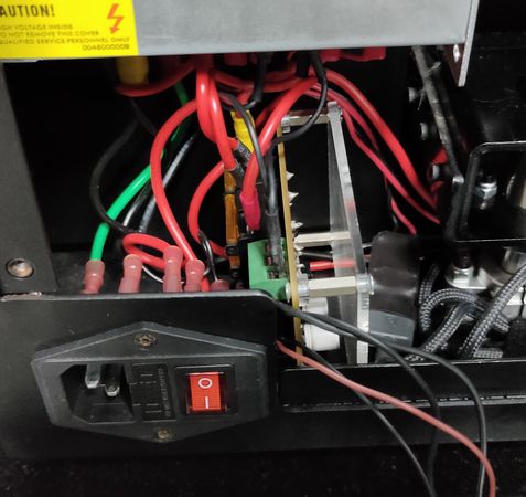
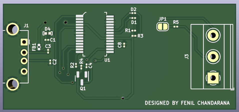
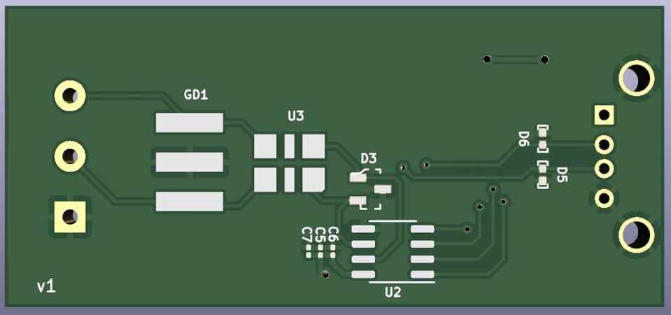
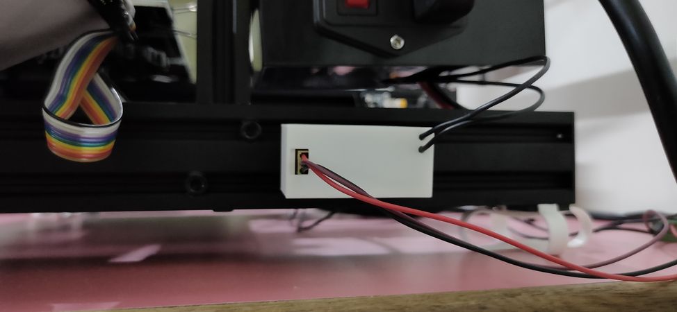
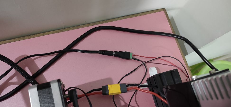
Auto shutdown - Invasive
A device that automatically shuts down the 3D printer after the printing job is done.
Here is the working of the device in different 3D printers,
About the project: This is a PCB designing project consisting of designing and fabricating a device which can
detect when the printing job is done and after the detection it will shutdown the 3D printer.
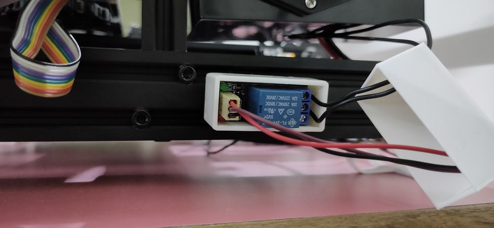
This device works like an add-on for your Power supply unit. So it will work on any 3D printer. Here is the device installed in Julia Avanced,
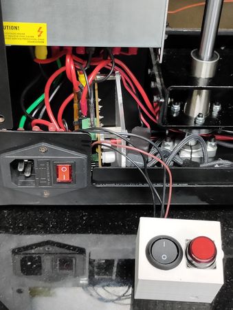
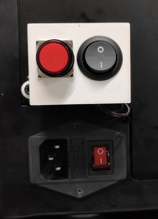
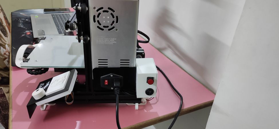
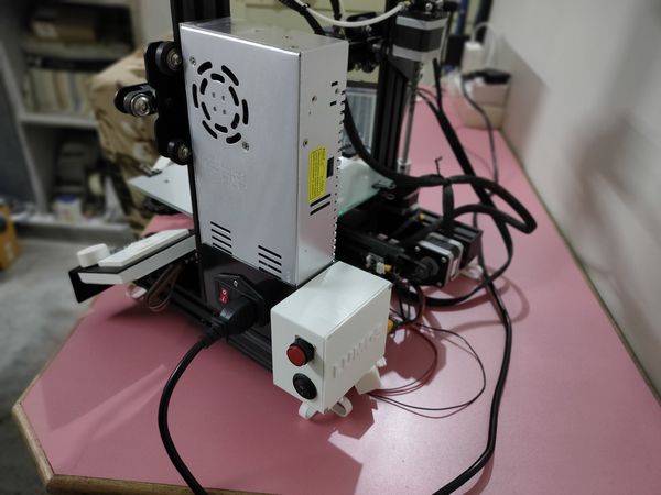
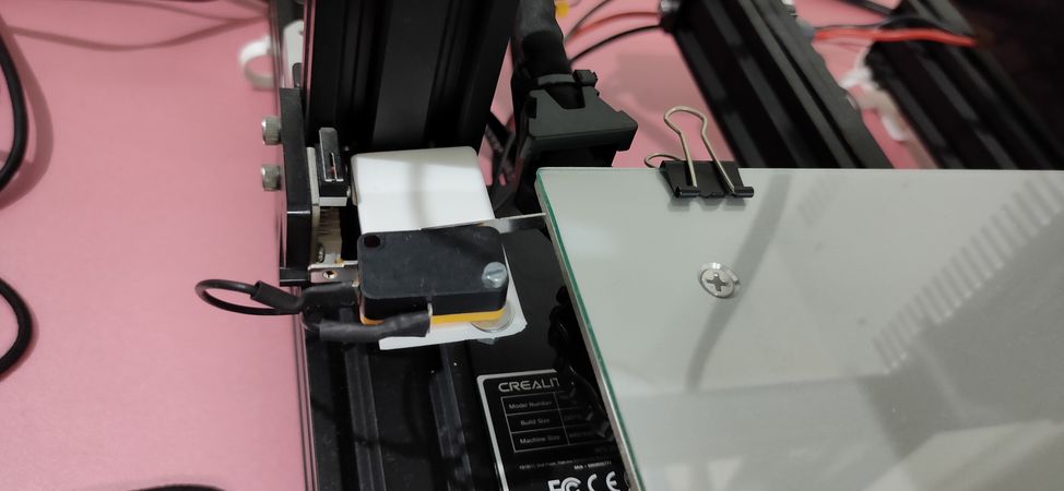
Here is the device installed in Creality Ender 3
The device is supposed to be connected in series between the PSU and 3D printer. The device has the option to enable or
disable the Auto shutdown function, it will only shut down the printer automatically if you have turned on the
device's SPST switch.
Once installed, keep the switch on the PSU of the printer always on and in order to turn on printer, press the device's push button and
in order to manually shutdown the printer, turn off the PSU switch. For the easy installation, set of wires connected with
terminal connectors, push button, SPST switch along with its housing will be provided.
Refer to the image given below for installing the device in your Julia advanced 3D printer,
design a diagram
Refer to the image given below for installing the device in your Creality ender 3 3D printer,
design a diagram
This project was developed with the help of Design and Making lab and Microfactory (Makerspace) IIT Bombay. Microfactory
provided the micro-milling machine to mill the intital test PCBs and Design and Making lab provided the 3D printing
machine to test those milled
PCBs.
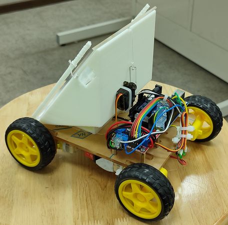
Line following bot w/ dumping mechanism
A bot on wheels that follows white line, inclines 10°, 20° & 30° slope and
dumps the payload at the end. Here is the working of the bot:
About the project:
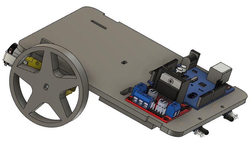
This is a line following bot that follows the white line and having a simple mechanism to dump the payload(pebbles). It's a 4 wheel drive bot, since the
purpose of the bot was to dump the payload after inclining multiple degrees of slope ranging 10°, 20° & 30°.
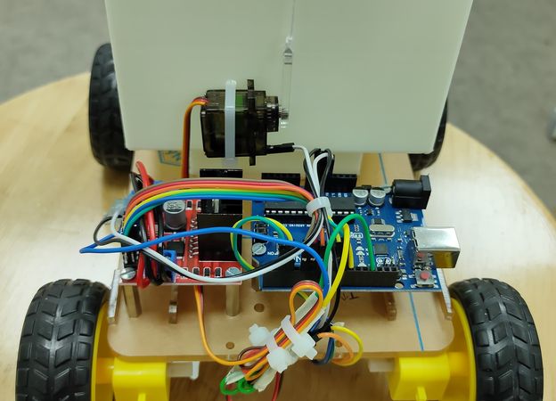
For the electronics I have used:
4x 100RPM BO motors
1x L293D motor driver
1x Arduino UNO
2x IR sensor module
1x MG90 servo motor
1x SPST Switch
3x 3.3V Rechargable battery(battery pack)
4x Wheels
Bolts, nuts and standoff spacers
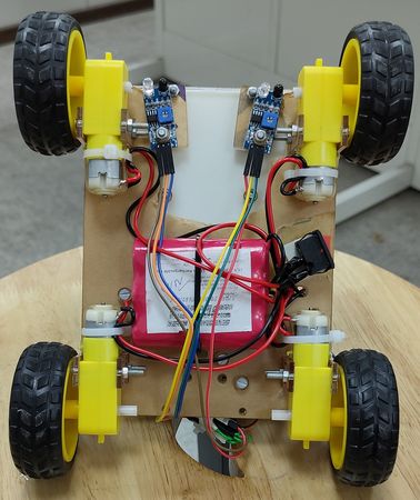
To detect the white line, I have used 2 IR module and arranged them at a distance so that the white line falls between the two module
To drive the wheels I have used 4 100RPM BO motors, which is driven by L293D motor driver.
For the microcontroller I have used Arduino UNO which sends the signal to the motor driver
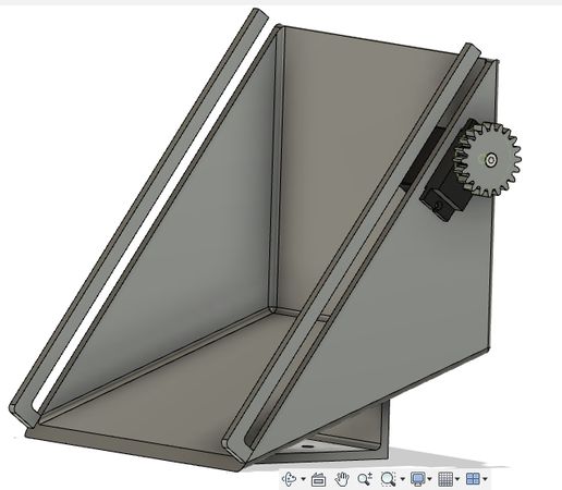
To lift the lid the container, I have used MG90 servo motor(I would recommend using MG995 instead, more reliable)
Here is the schematic diagram of the connections:
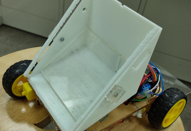
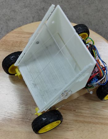
Here are some shots of the bot:
I used a L shape clamp to restrict the movement of the lid horizantally,
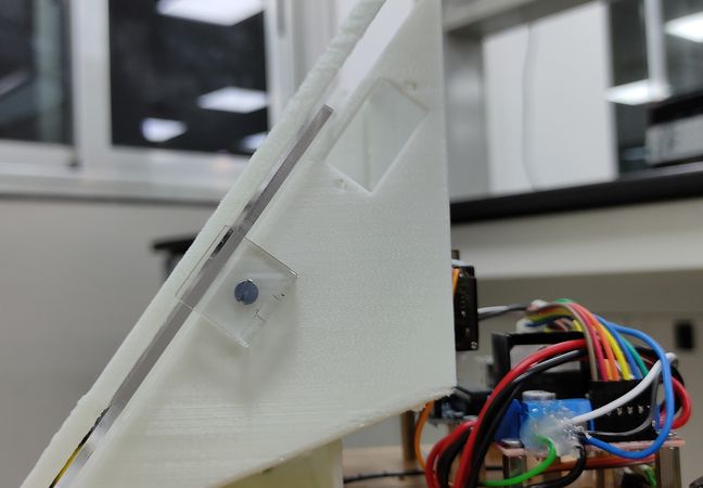
used a small piece of acrylic sheet and placed it at an angle inside the container so that the pebbles slides easily,
Here is the working of the dumping mechanism:
The code i used for the programming:
I fabricated the container using a 3D printer and fabricated the lid and chassis using laser cutter
You can download the files necessary for fabrication like STL and DXF from here
Item count
A device that counts the number of items from its stack, and also keeps track of the total number when the items are counted in batches
About the project:
This project was developed during my time at FLAME University
and serves solely as a demonstration of my work.
All rights to the project are owned by the university.
Click here to go back to the top
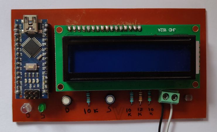
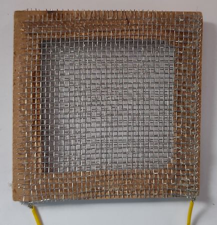
Water leak detection
A device that detects when there is a water leakage in the taps:
About the project:
Back in 2017, I participated in an even called
https://www.techstars.com/communities/startup-weekend
where you need to pitch an idea, work on that idea as a team, build the product and pitch the product to potential investors, all this in 3 days.
This was just to give you a glimpse of a startup world. I pitched the idea of detecting water leak from the taps in public places. My idea didn't
get selected, but I chose to work on the project for a few months and I ended up with a very basic proof-of-concept model. The device basically
detects the continuity of two electrodes, meaning when the water will pass through those two electrodes, microcontroller will know there is a
leak and start recording the data.
Provision of two electrodes for the water to pass,
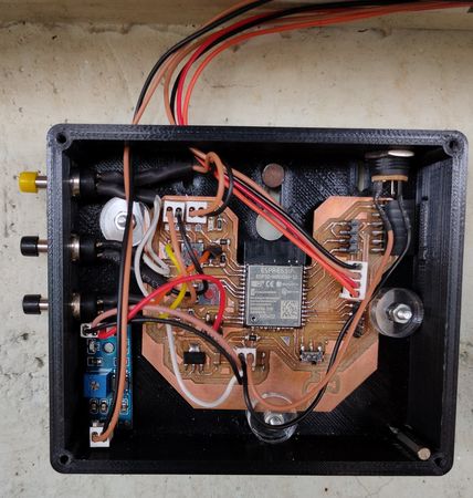
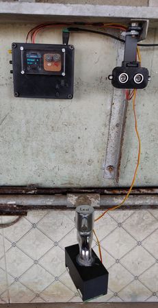
During my
Fab Academy
journey, for the final project, I choose to persue this project with more advancements with the aim to make it a finished-ready to sell device.
I was able to achieve some part of the desired goal,
Lantern
A lantern with a novel ON/OFF mechanism,
About the project:
This project was developed during my time at FLAME University
and serves solely as a demonstration of my work.
All rights to the project are owned by the university.
Click here to go back to the top
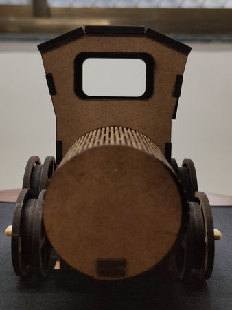
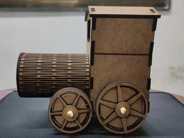
Locomotive
A vintage locomotive designed in multiple parts, fabricated in laser cutter and then
assembed. Here is the glimpse of the locomotive:
About the project:
The inspiration of making this came from the store ugears and was suggested to me by
Prof. Ankit Jain.
I took the reference of this locomotive:

I then designed the locomotive in a way that I can later fabricate them using laser cutter.
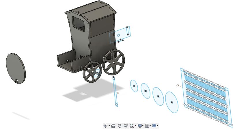
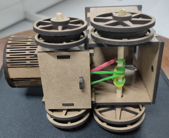
The locomotive is assembled using different press-fit
joints like finger joint and wedge joint:
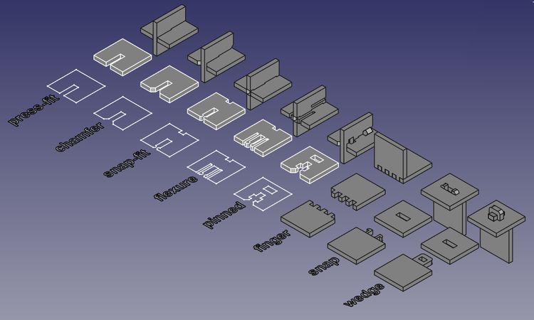
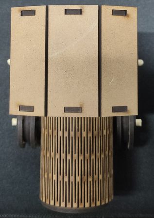
It also has a living hinge feature to make the cylindrical front part of the engine. Here are some snapshots of the locomotive:
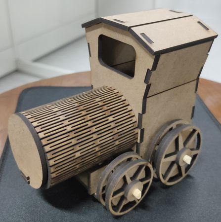
I used thin wooden sticks and rubber band so that when the locomotive is pulled and released, it will automatically move forward.
You can download the DXF files for fabricating the locomotive from here
Line following bot - Basic version
A basic verison of line following bot which follows the path of the black line:
About the project:
While working on the project, I wanted to achieve two things: make the bot as small as possible and use Infrared LEDs instead of using a module.
I started with soldering the IR LEDs with resistor to make it work like an IR module but without potentiometer to set the sensitivity,
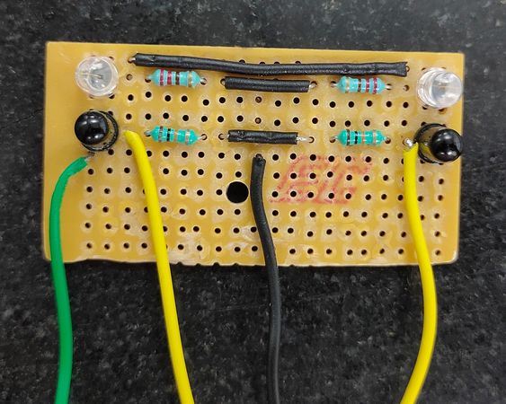
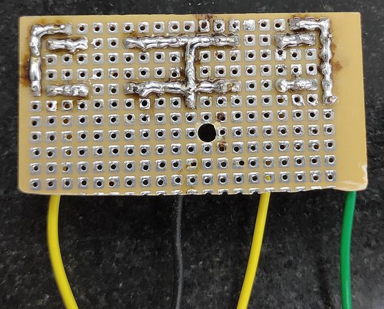
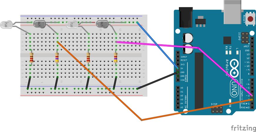
Here is the schematic diagram for the IR LEDs,
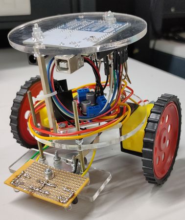
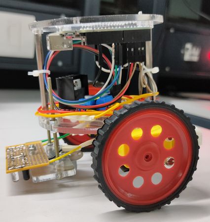
The chassis is just 100mm in size. To run the bot, I wasn't using any battery, insted I was using DC power supply. Here are some snapshots of
the bot:
For the electronics I have used:
2x 100RPM BO motors
1x L293D motor driver
1x Arduino UNO
2x Pair of IR LEDs with resistor(PCB)
2x Wheels
1x Caster wheels
Bolts nuts and standoff spacers
To detect the black line, I mounted the PCB onto the bot where the pair of IR LEDs is fixed at distance, between which bot is suppose to follow
the black line
To drive the wheels I have used 2 100RPM BO motors, which is driven by L293D motor driver.
For the microcontroller I have used Arduino UNO which sends the signal to the motor driver
.
Here is the schematic diagram of the connections:
The code I used for the programming:
For more details, visit the instructable page:
https://www.instructables.com/Line-Following-Bot/
Industrial USB to RS485 Bidirectoinal Converter
An industrial grade USB to RS485 bidirectional converter:

About the project:
This is a PCB designing project that I took as free lancing. I took the refrence of
Waveshare's USB to RS485
Auto shutdown - Limit switch
Limit switch that automatically shuts down the 3D printer(Ender 3)
after the printing is done:
About the project:
In all the 3D printers, after the printing job is done, the printer will stay on(the always on fan, display, microcontroller) until you manually
turn them off. I didn't want my 3D printer to unnecessarily stay on and because of that I had to schedule the print job according to the print time.
So I installed a limit switch on the printer in a way that after the printing job is done, the bed will move forward on the Yaxis and hit the
limit switch,
The limit switch will cause the relay module to trigger,
The relay is conntected with the AC supply line in series that powers the 3D printer and when the limit switch triggers the relay module, it will
break the connection of AC power supply, thus causing the printer to shut down. The relay is getting external 5V supply(you can even use a buck
converter),
For more details, visit my instructable webpage: https://www.instructables.com/Ender-3-Auto-Shutdown/
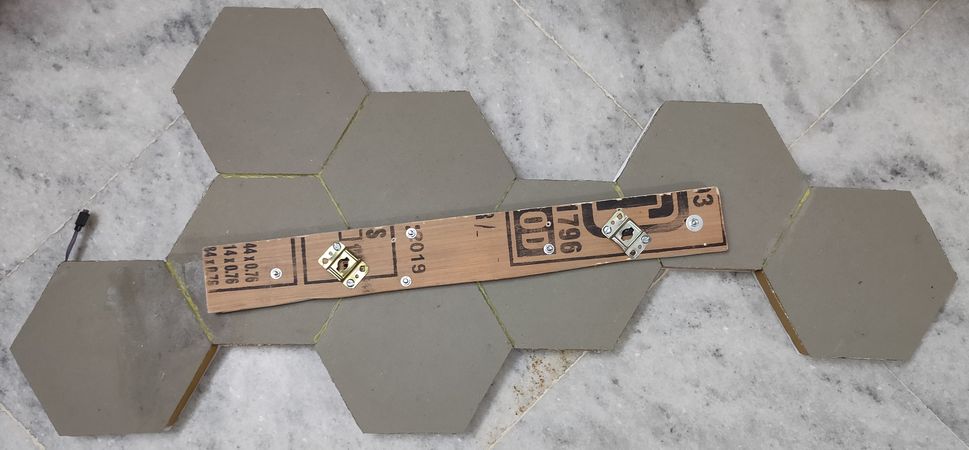
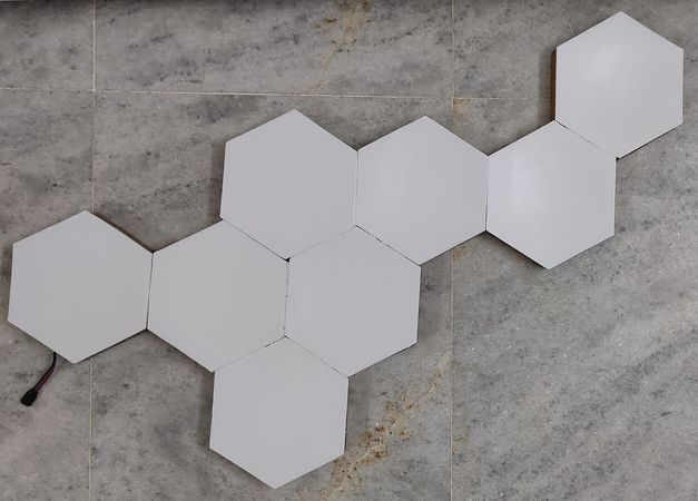
NanoLeaf
A NanoLeaf made of multiple hexagon shape blocks with LED strip inside:
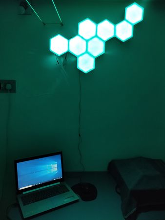
About the project:
I cut multiple pieces of hexagon shapes from cardboard and then stick the boundry of the hexagon block made of corrugated sheet,
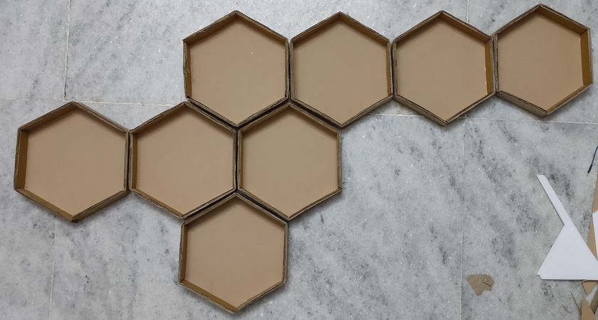
stick the hexagon blocks together with adhesive and attached a wooden block behind for better strength,
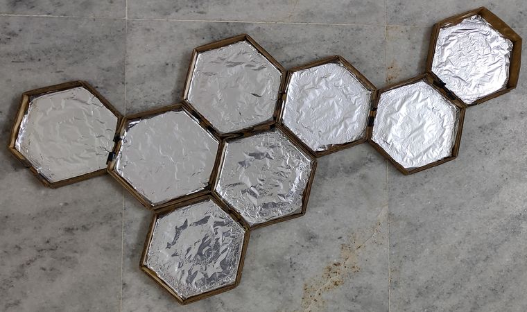
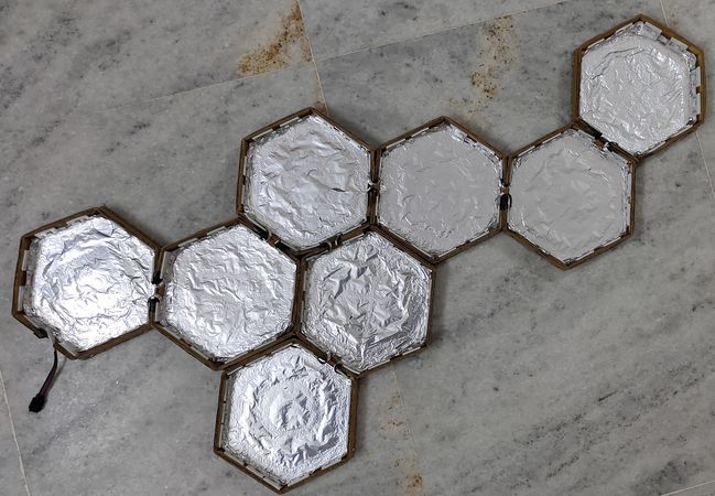
stick aluminium foil on the cardboard for better reflection,
made slits on the boundry and routed LED strip through all the hexagon blocks,
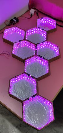
added thermocol sheets to diffuse the light,
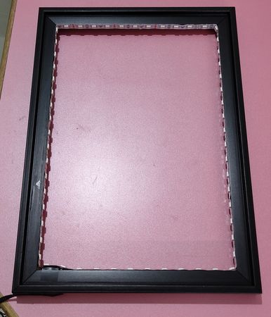
Infinity mirror
An optical illusion which looks like an infinite tunnel,
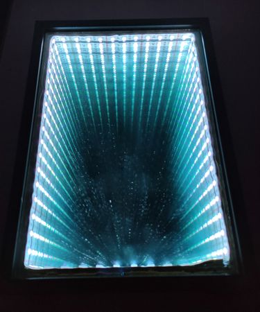
About the project:
After making the NanoLeaf, I still had some LED strip left, so I thought to make use of it by making an INfinity mirror. The principle of
infinity mirror is simple: Place LED between a normal mirror and a two way mirror and it will give you an effect of a infinity tunnel.
I just purchased a photo frame, stick the LED strip inside the frame and stick normal mirror on the back and two way mirror on the front,
Match the following
A device that will give you a feedback if you match the image with the text correctly!
About the project:
This was my first DIY project that I made when I was in 7th grade. The image is connected with the text through wire. Now when you connect the
battery, LED and image-text(wire) in series, you complete the circuit and you get a feedback if the match is correct.